

Chain shaft of chain saw
A chain shaft and chain saw technology, applied in the field of machinery, can solve the problems of production waste, increase production cost, uneven stress distribution on the head of the chain shaft, etc., and achieve the effect of reducing production cost and improving production efficiency.
Inactive Publication Date: 2012-11-28
SHANGHAI JIAO TONG UNIV
View PDF7 Cites 3 Cited by
- Summary
- Abstract
- Description
- Claims
- Application Information
AI Technical Summary
Problems solved by technology
Because the frustum-shaped edge protrudes, stress concentration occurs at the contact between the edge and the riveting wheel during the riveting process, making the riveting wheel of the riveting machine vulnerable to damage, and its effective service life is only a few hours, while the value of a riveting wheel is hundreds of On the one hand, it causes a lot of waste in production and increases the production cost; on the other hand, the stress distribution of the head of the chain shaft after the riveting is uneven, the riveting effect is not good, and it is easy to fall off
Method used
View moreImage
Smart ImageViewing Examples

Examples
Embodiment 1
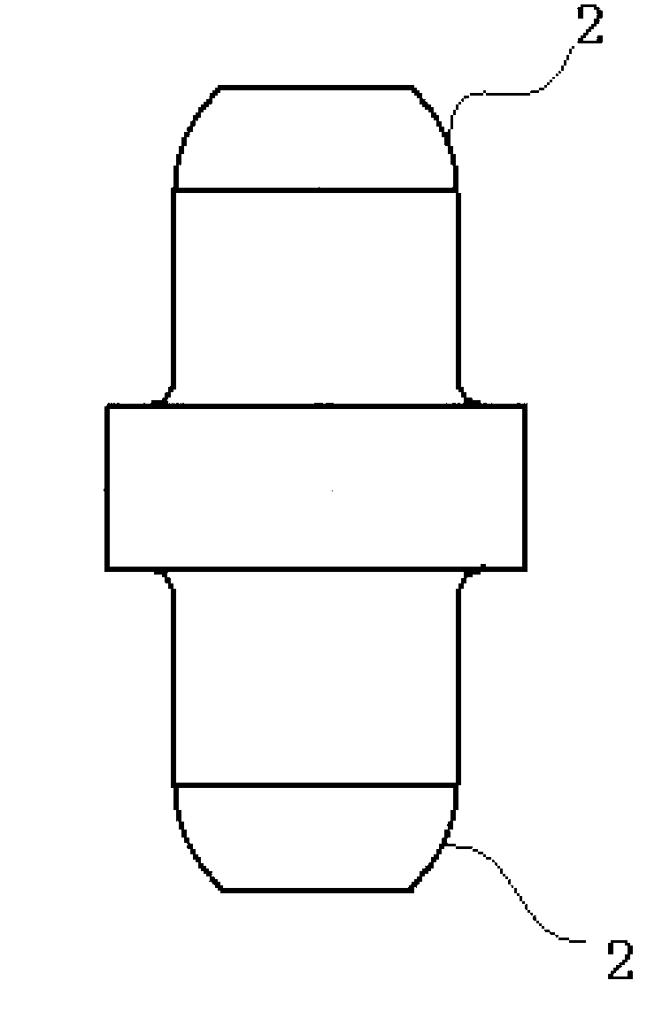
[0017] Because the head of the chain shaft in Example 1 adopts a circular arc wave structure, the problem that the riveting wheel is easily damaged during the riveting process of the riveting machine is solved, the production efficiency is improved, and the production cost is reduced.
Embodiment 2
[0018] Embodiment 2, the end of the chain saw chain shaft can be hemispherical, so as to adapt to the riveting wheel of the same shape.
Embodiment 3
[0019] Embodiment 3, the end of the chain shaft of the chain saw can be a circular frustum with an arc-shaped side surface, so as to be compatible with the riveting wheel of the same shape.
Login to View More PUM
 Abstract
The invention discloses a chain shaft of a chain saw. The chain shaft of the chain saw comprises two ends and a peripheral surface around a central axis of the chain shaft, and is characterized in that the each end comprises the peripheral surface with a certain curvature. The chain shaft provided by the invention can ensure that the stress is uniformly distributed on the head of the chain shaft subjected to a cold heading process and the stress is uniformly distributed on the surface of a riveting wheel of a riveting machine in the process of spin riveting, so that the probability of damaging the chain shaft is reduced and the production cost is effectively lowered.
Description
technical field [0001] The invention relates to the technical field of machinery, in particular to a chain saw chain shaft. Background technique [0002] In the production process of modern chain saws, one of the steps is to install the chain shaft into the shaft hole on the moving piece and the connecting piece, and then use a riveting machine to rivet the end of the chain shaft, which belongs to a cold heading process. The two ends of the traditional chain shaft are truncated cones. During the riveting process, due to the high speed of the riveting wheel, which reaches 1200 r / min, the riveting time is short, and huge pressure is generated instantly to deform the end of the chain shaft into a disc shape. Because the frustum-shaped edge protrudes, stress concentration occurs at the contact between the edge and the riveting wheel during the riveting process, making the riveting wheel of the riveting machine vulnerable to damage, and its effective service life is only a few h...
Claims
Login to View More Application Information
Patent Timeline
 IPC IPC(8): F16G15/02
Inventor秦计生彭雄奇王俊园秦鸣泓
OwnerSHANGHAI JIAO TONG UNIV