Air-conditioning outdoor unit condenser and air-conditioning outdoor unit with condenser

A technology for outdoor units and condensers of air conditioners, applied in evaporators/condensers, refrigerators, refrigeration components, etc., can solve the problems of low-temperature heating capacity and low energy efficiency ratio in all seasons, and achieve the effect of increasing APF value

Inactive Publication Date: 2012-11-28
广东科龙嘉科电子有限公司
View PDF3 Cites 12 Cited by
  • Summary
  • Abstract
  • Description
  • Claims
  • Application Information

AI Technical Summary

Problems solved by technology

[0005] The invention provides a condenser of an outdoor unit of an air conditioner and an outdoor unit of an air conditioner equipped with the condenser, which can solve the problem of the low-temperature heating capacity and the annual seasonal energy efficiency ratio of the existing outdoor unit of an air conditioner meeting the evaluation level of energy efficiency ratio in cooling seasons. high problem

Method used


Image

  • Air-conditioning outdoor unit condenser and air-conditioning outdoor unit with condenser
  • Air-conditioning outdoor unit condenser and air-conditioning outdoor unit with condenser
  • Air-conditioning outdoor unit condenser and air-conditioning outdoor unit with condenser

Examples


Embodiment 1

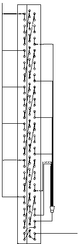
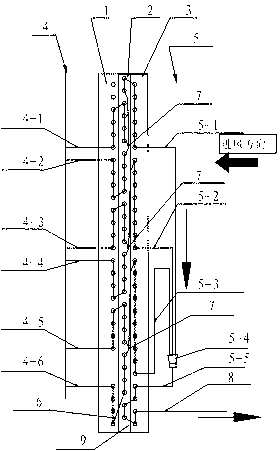
[0034] refer to figure 2 , an air conditioner outdoor unit condenser, including three rows of condenser components composed of aluminum foil fins and 40 U-shaped internal thread copper pipes, an inlet pipe assembly 4, an elbow 6, a U-shaped tee assembly, and an air outlet pipe assembly 5 And the total outlet pipe 8, the three rows of condenser assemblies are the inner row 1 located on the leeward side of the condenser, the middle row 2 and the outer row 3 located on the windward side of the condenser, wherein the intake pipe assembly 4 located on the leeward side of the condenser includes 6 branch routes, namely the first branch route 4-1, the second branch route 4-2, the third branch route 4-3, the fourth branch route 4-4, and the fifth branch route 4 -5. The sixth branch inlet 4-6, correspondingly, the air outlet pipe assembly 5 located on the windward side of the condenser includes three branch outlets, which are respectively the first branch outlet 5-1, the second branch ...

Embodiment 2

[0047] Such as image 3 As shown, the difference from Embodiment 1 is the arrangement of three process branches,

[0048] Such as Figure 7 As shown, the flow arrangement of the first flow branch is as follows:

[0049] The first branch route 4-1 connects the two U-shaped internal thread copper pipes located in the inner row 1 of the condenser from bottom to top, connects to the middle row 2 through the elbow 6, and connects the three U-shaped internal threads of the middle row 2 The copper pipes are connected from top to bottom to form a " ”-shaped process, the second branch route 4-2 connects the two U-shaped internal thread copper pipes located in the inner row 1 of the condenser from top to bottom, connects to the middle row 2 through the elbow 6, and connects the middle row 2 Two U-shaped internal threaded copper pipes are connected from bottom to top to form a "U"-shaped process. The first and second branch routes 4-1 and 4-2 are aggregated into one road through the ...

Embodiment 3

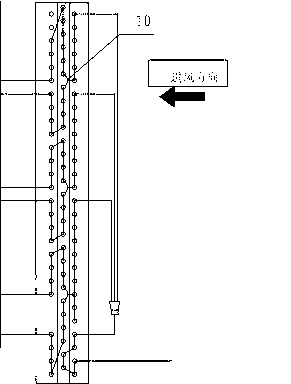
[0055] Such as Figure 4 As shown, the only difference from Embodiment 1 is that the third branch approach 4-3 and the fourth branch approach 4-4 in the second process branch are aggregated into one road through the claw-shaped tee 10 in the middle row, and the aggregate To the outer row 3, the four U-shaped internal thread copper pipes of the outer row 3 are connected from bottom to top, and finally aggregated to the second branch outlet 5-2.

[0056] The processes of the first and third process branches are the same as those of the first and third process branches in Embodiment 1.


PUM


Abstract

The invention provides an air-conditioning outdoor unit condenser which comprises three rows of condenser components, an air inlet pipe assembly, an elbow, a three-way assembly, an air outlet assembly and a main outlet pipe, wherein the air inlet pipe assembly is located at the leeward side of the condenser, and the air outlet pipe assembly is located at the windward side of the condenser; and the condenser comprises a plurality of flow branches, each flow branch comprises two sequentially adjacent branch inlet routes, a plurality of U-shaped inner-thread copper pipes, elbows, three-way assemblies and one branch outlet route through connection, the quantity of the branch inlet routes is an even number, the quantity of the branch outlet routes is 1/2 of that of the branch inlet routes, and the bottommost part of the flow branch is the supercooling section of the condenser. The invention also provides an air-conditioning outdoor unit using the condenser. Experimental tests show that the rated heating capacity, the low-temperature heating capacity and the energy efficiency ratio of the air-conditioning outdoor unit using the condenser are greatly increased, and the heating quantity is increased by 5-10%.

Description

technical field [0001] The invention belongs to the technical field of air-conditioning and refrigeration engineering, and in particular relates to an improvement of the condenser structure of an air-conditioning outdoor unit. Background technique [0002] China's household inverter air conditioners currently use SEER as the grade evaluation standard for cooling seasons. In order to be in line with international standards, the new energy efficiency standard that is currently being approved will use APF as the energy efficiency grade evaluation standard, and the energy efficiency requirements are higher. APF is the annual seasonal energy efficiency ratio, which is the comprehensive annual (cooling and heating) seasonal energy efficiency ratio. [0003] Therefore, when SEER cooling season energy efficiency ratio is used as the evaluation level, the design of air conditioner manufacturers generally takes the best cooling energy efficiency as the priority design principle. Since...

Claims


Application Information

Patent Timeline
Patent Type & Authority Applications(China)
IPC IPC(8): F24F13/30F25B39/04
Inventor 王军刘通
Owner 广东科龙嘉科电子有限公司
Why Eureka
Try Eureka