Eureka AIR delivers breakthrough ideas for toughest innovation challenges, trusted by R&D personnel around the world.

Method for measuring pressure in rotating state

A technology of rotating state and measuring method, which is applied in the direction of measuring device, measuring fluid pressure, measuring fluid pressure through electromagnetic components, etc., can solve problems such as gas leakage, and achieve the effect of ensuring accuracy and simplifying measuring structure.

Inactive Publication Date: 2014-04-02
BEIHANG UNIV
View PDF7 Cites 1 Cited by
  • Summary
  • Abstract
  • Description
  • Claims
  • Application Information

AI Technical Summary

Problems solved by technology

[0007] In order to solve the problems existing in the prior art, the present invention proposes a pressure measurement method in a rotating state that is easy to operate and whose precision is easy to ensure, and overcomes the gas in the dynamic and static interfaces or pressure-taking tubes, pressure-taking plates and other equipment that exist during the measurement process. Leakage problem, calibrate the strain gauge pressure sensor in the rotating state to obtain the calibration curve of the corresponding relationship between the sensor output signal and the actual pressure value at different speeds, and use the calibration curve to obtain the accurate pressure in the rotating state

Method used


Image

  • Method for measuring pressure in rotating state
  • Method for measuring pressure in rotating state
  • Method for measuring pressure in rotating state

Examples


Embodiment Construction

[0034] The present invention will be further described in detail below in conjunction with the accompanying drawings.

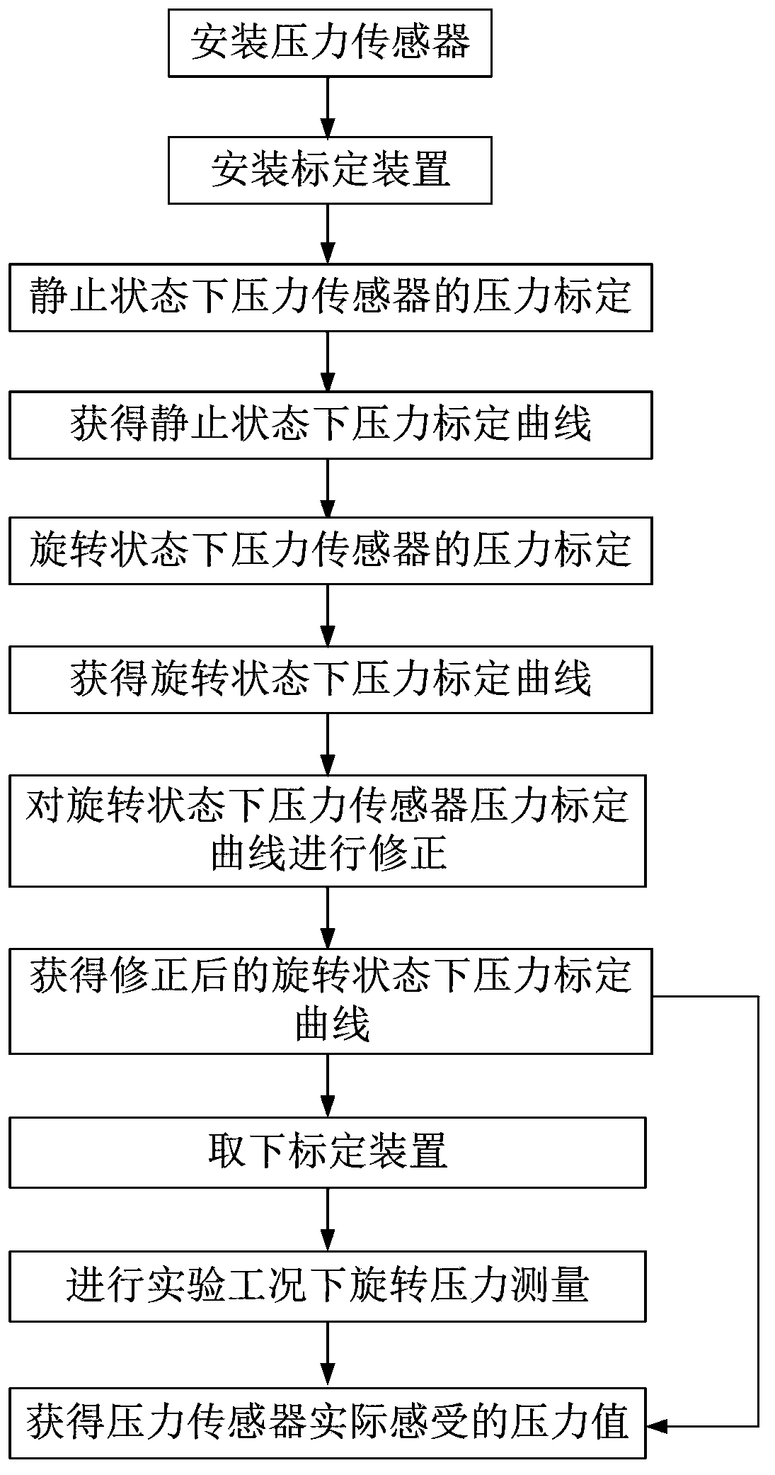
[0035] The present invention is a pressure measurement method in a rotating state, such as figure 1 shown, through the following steps:

[0036] Step 1: installation of pressure sensor 2;

[0037] The pressure sensor 2 is installed in the sensor installation hole opened on the test piece 1 through the two sides to measure the pressure distribution of the tested surface of the test piece 1 . The pressure sensor 2 is a strain gauge pressure sensor 2 with low inertia and high sensitivity. Its working principle is that the pressure-sensitive diaphragm is deformed when subjected to a certain pressure, and the deformation causes the output signal to change. Since the pressure sensor 2 rotates together with the rotating test piece 1 in the actual working condition of the pressure measurement experiment in the rotating state, the deformation of the pressure-sensiti...


PUM


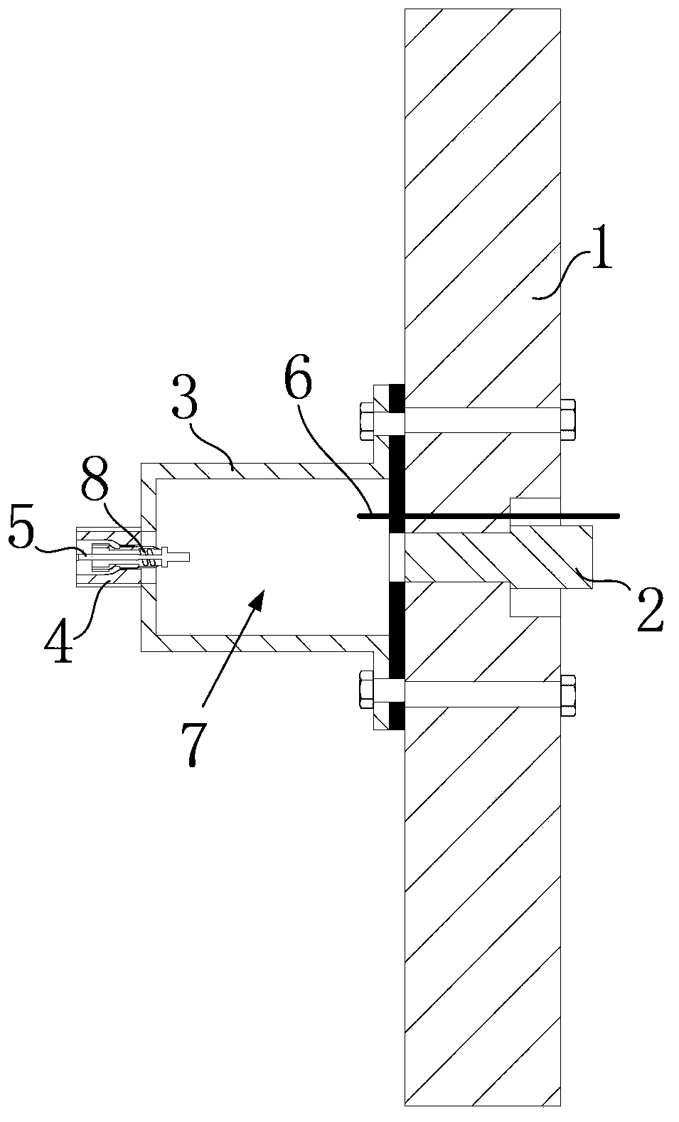
Abstract

The invention discloses a method for measuring pressure in a rotating state. The method comprises: installing a demarcating device on a test piece to form a pressure-tight demarcating chamber, feeding gas into the demarcating chamber, measuring voltage signal values of a sensor and gas pressure values of the corresponding chamber, fitting a curve to obtain a pressure calibration curve in a stationary state; feeding gases with different pressures in the demarcating chamber and rotating the test piece at different rotating speed, measuring the voltage signal values of the sensor corresponding the gas pressure in the present demarcating chamber under each rotating speed, fitting a curve to obtain a pressure calibration curve in the rotating state; obtaining an actual pressure value of the demarcating chamber through temperature of the demarcating chamber under each rotating speed, and modifying the pressure calibration curve in the rotating state; and combining the modified calibration curve and the signal values under each rotating speed measured by the pressure sensor in a test condition to obtain an actual pressure value of the pressure sensor. The method for measuring pressure in the rotating state makes test results capable of being reference, and ensures measuring precision of the test at the same time.

Description

technical field [0001] The present invention relates to the field of pressure measurement. Specifically, the strain gauge pressure sensor is calibrated in the rotating state to obtain the calibration curve of the corresponding relationship between the output signal of the sensor and the actual pressure value at different speeds. Using the calibration curve, the rotation can be accurately measured. It is especially suitable for pressure measurement of rotating parts such as aeroengine turbine disks. Background technique [0002] With the advancement of technology, increasing the gas temperature before the turbine has become an important way to improve the performance of modern aero-engines, but at the same time it will also cause negative effects such as excessive heat load on the turbine disk. In order to ensure the safe and reliable operation of the turbine, in addition to improving the turbine material, the cooling of the turbine disk is also very important. In order to i...

Claims


Application Information

Patent Timeline
Patent Type & Authority Patents(China)
IPC IPC(8): G01L9/00G01L27/00
Inventor 罗翔徐国强李登超蔡旭张达
Owner BEIHANG UNIV
Why Eureka
Eureka Blog
Learn More