High-power IGBT drive circuit

A high-power, high-resistance technology, applied in the field of high-power IGBT drive circuits, can solve the problems of low drive power, low switching frequency, and high price, and achieve the effect of strong drive capability and high switching frequency

Inactive Publication Date: 2012-11-28
WEIFANG UNIVERSITY
View PDF3 Cites 2 Cited by
  • Summary
  • Abstract
  • Description
  • Claims
  • Application Information

AI Technical Summary

Problems solved by technology

[0002] The existing high-power IGBT (Insulated Gate Bipolar Transistor, Insulated Gate Bipolar Transistor) drive

Method used


Image

  • High-power IGBT drive circuit

Examples


Example Embodiment

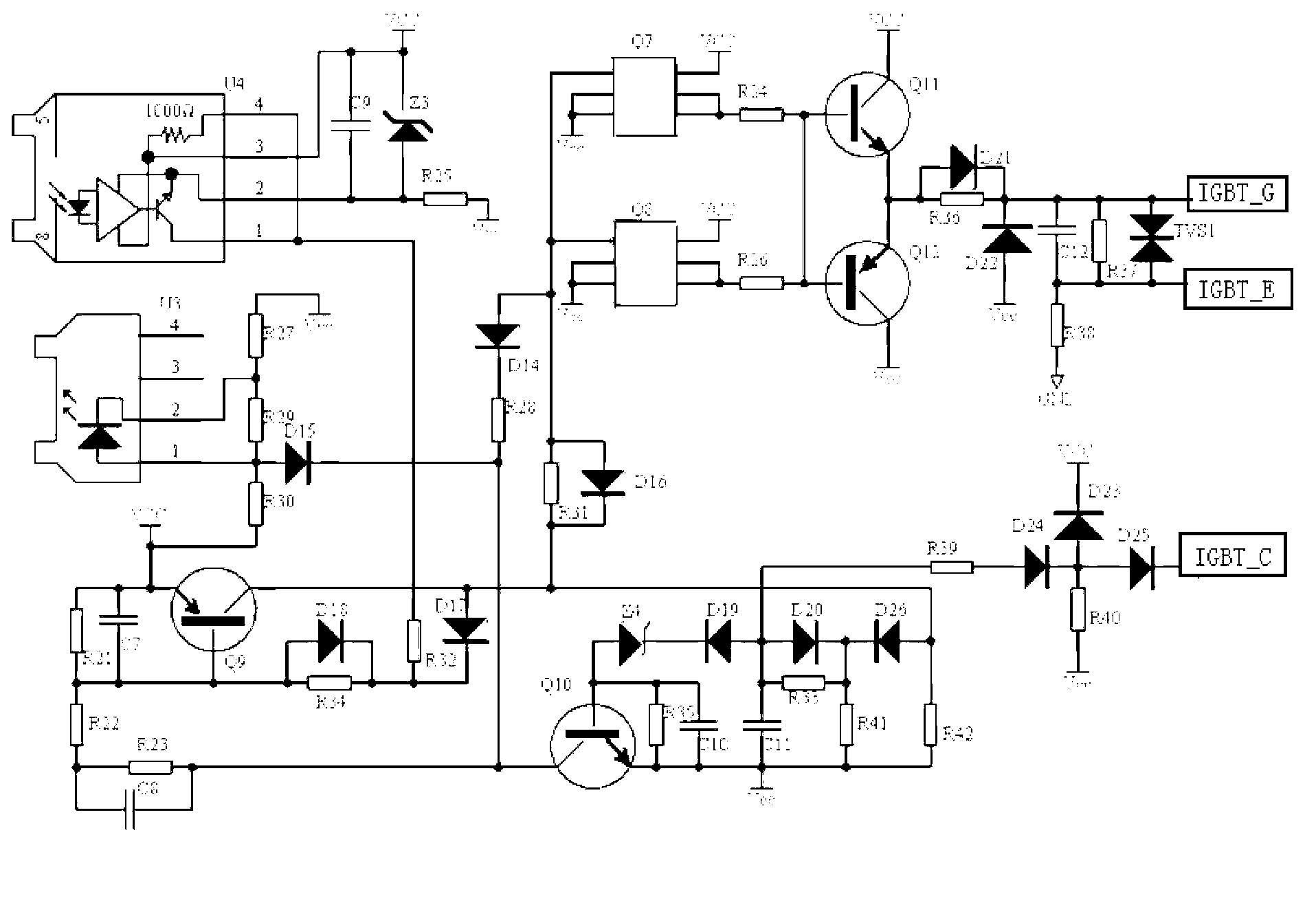
[0007] Hereinafter, preferred embodiments of the present invention are given in conjunction with the drawings to illustrate the technical solutions of the present invention in detail.

[0008] Such as figure 1 As shown, the high-power IGBT drive circuit of the present invention includes a seventh integrated transistor array Q7, an eighth integrated transistor array Q8, a ninth transistor Q9, a thirteenth transistor Q10, an eleventh transistor Q11, and a twelfth integrated transistor array Q7. Transistor Q12, 22nd resistor R22, 23rd resistor R23, 24th resistor R24, 26th resistor R26, 28th resistor R28, 31st resistor R31, 30th resistor Three resistors R33, thirty-ninth resistor R39, forty-second resistor R42, fourteenth diode D14, twenty-first diode D21, twenty-fourth diode D24, twenty-fifth diode The tube D25, the twenty-sixth diode D26, the eighth capacitor C8, the tenth capacitor C10, the eleventh capacitor C11, the fourth voltage regulator Z4, and the ninth transistor Q9 are c...


PUM


Abstract

The invention discloses a high-power insulated gate bipolar translator (IGBT) drive circuit, which comprises a seventh integrated triode array and other components, wherein a ninth triode is connected with a thirty-first resistor; the thirty-first resistor is connected with the seventh integrated triode array, an eighth integrated triode array and a fourteenth diode; a twenty-eighth resistor is connected with the fourteenth diode; the seventh integrated triode array is connected with an eleventh triode; the eighth integrated triode array is connected with a twelfth triode; the twenty-eighth resistor is connected with a tenth triode and a twenty-third resistor; the twenty-third resistor is connected with a twenty-second resistor and an eighth capacitor; a twenty-fourth resistor is connected between the seventh integrated triode array and the eleventh triode; a twenty-sixth resistor is connected between the eighth integrated triode array and the twelfth triode; and the tenth triode is connected with a tenth capacitor, an eleventh capacitor and a fourth voltage-regulator tube. The high-power IGBT drive circuit implements fiber-optic isolation, and has high switching frequency and strong driving capability.

Description

technical field [0001] The invention relates to a driving circuit, in particular to a high-power IGBT driving circuit. Background technique [0002] The existing high-power IGBT (Insulated Gate Bipolar Transistor, Insulated Gate Bipolar Transistor) drive circuits are all imported drive circuit boards, with high prices, low switching frequency, and low drive power. Contents of the invention [0003] The technical problem to be solved by the present invention is to provide a high-power IGBT driving circuit, which realizes optical fiber isolation, high switching frequency and strong driving capability. [0004] The present invention solves the above-mentioned technical problems through the following technical solutions: a high-power IGBT drive circuit, characterized in that it includes a seventh integrated triode array, an eighth integrated triode array, a ninth triode, a thirteenth Pole tube, eleventh triode tube, twelfth triode tube, twenty-second resistor, twenty-third re...

Claims


Application Information

Patent Timeline
IPC IPC(8): H03K17/567
Inventor 郭春华宗绪锋董辉史纪元王成端
Owner WEIFANG UNIVERSITY
Why Eureka
Try Eureka