Voltage generating circuit and ultrasonic diagnosing device

a voltage generation circuit and ultrasonic technology, applied in the direction of mechanical vibration separation, instruments, applications, etc., to achieve the effect of high output voltag

Active Publication Date: 2010-01-28
GE MEDICAL SYST GLOBAL TECH CO LLC
View PDF7 Cites 30 Cited by
  • Summary
  • Abstract
  • Description
  • Claims
  • Application Information

AI Technical Summary

Benefits of technology

[0006]Embodiments described herein provide a voltage generating circuit that generates a voltage for driving an ultrasonic oscillator and an ultrasonic diagnosing device having said voltage generating circuit. The voltage generating circuit and ultrasonic diagnosing device are th

Problems solved by technology

In addition, they can realize the above-mentioned miniaturization and thinn

Method used


Image

  • Voltage generating circuit and ultrasonic diagnosing device
  • Voltage generating circuit and ultrasonic diagnosing device
  • Voltage generating circuit and ultrasonic diagnosing device

Examples


Embodiment Construction

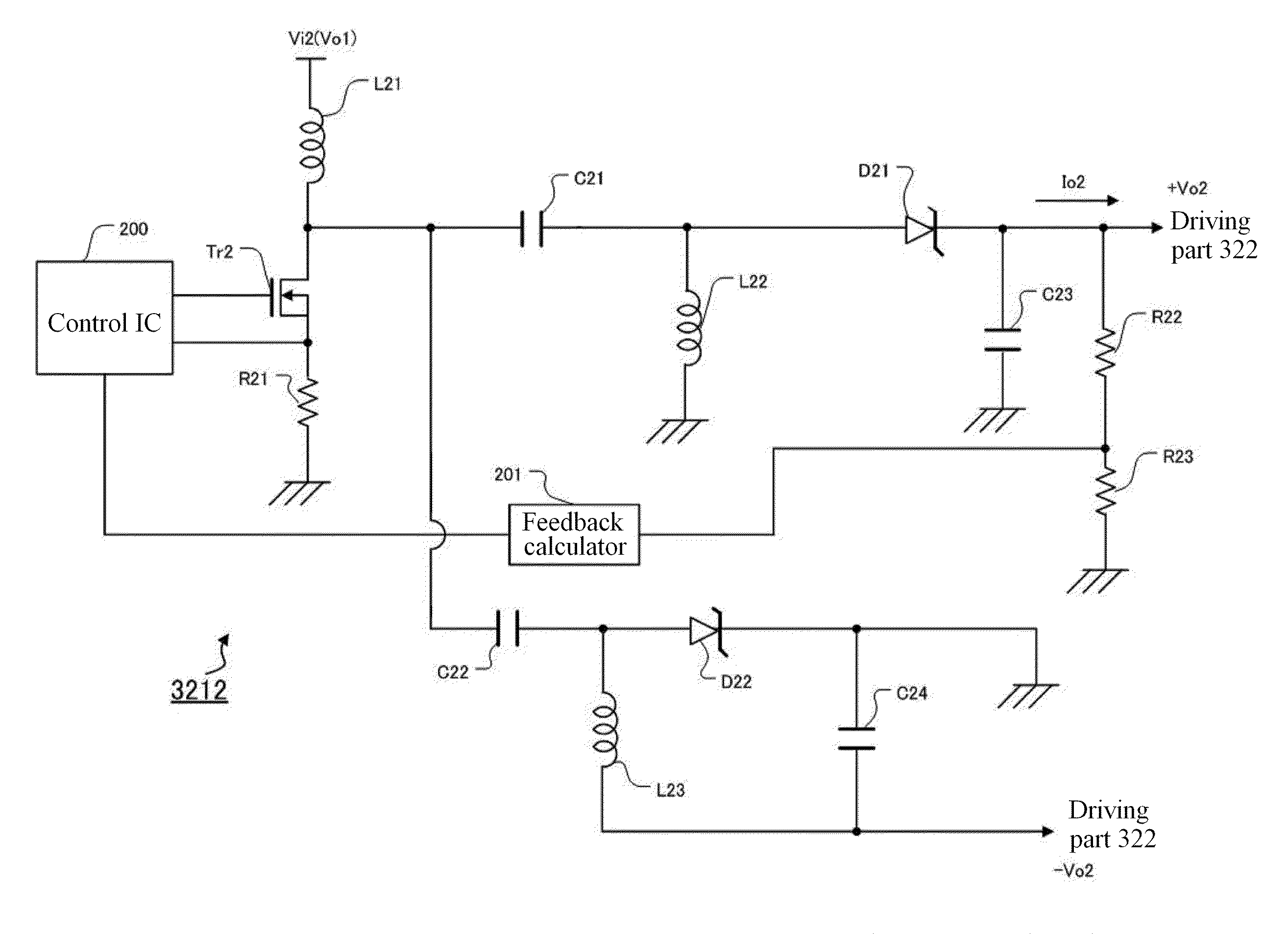
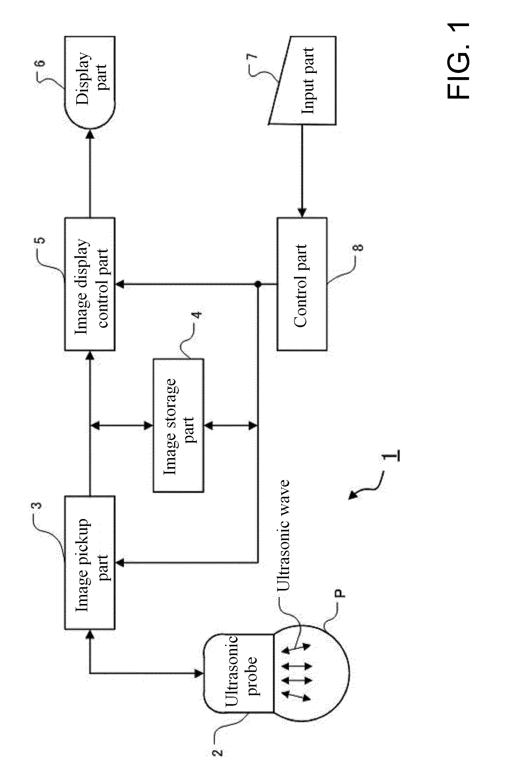
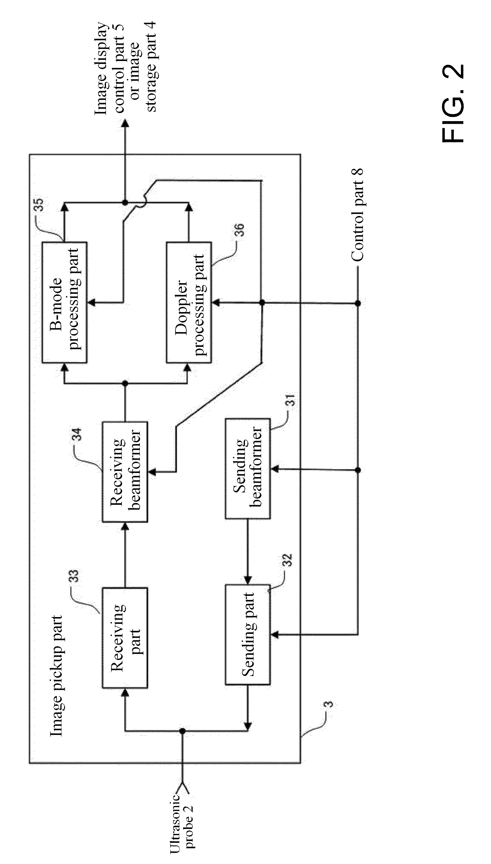
[0050]Embodiments of the invention will be described in detail below with reference to the accompanying drawings. FIG. 1 is a block diagram showing an example of an overall structure of an ultrasonic diagnosing device having the voltage generating circuit of the present invention. FIG. 2 is a block diagram showing a structure of an image acquiring part of the ultrasonic diagnosing device as shown in FIG. 1. FIG. 3 is a block diagram showing a structure of a sending part in the image acquiring part as shown in FIG. 2. FIG. 4 is a block diagram showing a structure of a voltage generating circuit in the sending part as shown in FIG. 3. FIG. 5 is a diagram showing a circuit structure of a boost converting circuit in the voltage generating circuit as shown in FIG. 4. FIG. 6 is a diagram showing a circuit structure of an SEPIC circuit in the voltage generating circuit as shown in FIG. 4.

[0051]An ultrasonic diagnosing device 1 as shown in FIG. 1 comprises an ultrasonic probe 2, an image ac...


PUM


Abstract

A voltage generating circuit generates a voltage for driving an ultrasonic oscillator, and includes a multi-stage connected power supply circuit without a transformer.

Description

FIELD OF THE INVENTION[0001]The embodiments described herein relate to a voltage generating circuit for generating a voltage that drives an ultrasonic oscillator, and to an ultrasonic diagnosing device.CROSS REFERENCE TO RELATED APPLICATIONS[0002]This application claims the benefit of Chinese Patent Application No. 200810134359.2 filed Jul. 24, 2008, which is hereby incorporated by reference in its entirety.BACKGROUND OF THE INVENTION[0003]In an ultrasonic diagnosing device, a voltage is applied to an ultrasonic oscillator made of a piezoelectric material to oscillate the same and thereby transmit an ultrasonic wave. Accordingly, the ultrasonic diagnosing device has a voltage generating circuit for generating a voltage that drives the ultrasonic oscillator. For example, reference can be made to the gazette of Japanese Laid-Open Patent Publication No. 2004-236869.[0004]In the case that, for example, a battery is used as a power supply of the voltage generating circuit, a voltage supp...

Claims


Application Information

Patent Timeline
IPC IPC(8): G05F1/10
CPCA61B8/06A61B8/467G01S7/52019G01S15/8979B06B1/0207A61B8/461A61B8/56
Inventor ZANG, XINPINGAMEMIYA, SHINICHI
Owner GE MEDICAL SYST GLOBAL TECH CO LLC
Why Eureka
Try Eureka