Control circuit for active clamp flyback power converter with predicted timing control

a technology of timing control and control circuit, which is applied in the direction of electric variable regulation, process and machine control, instruments, etc., can solve the problems of high power loss at light load, and the high efficiency of traditional active clamp circuits, and achieve the effect of high efficiency

Active Publication Date: 2014-10-16
SEMICON COMPONENTS IND LLC
View PDF2 Cites 30 Cited by
  • Summary
  • Abstract
  • Description
  • Claims
  • Application Information

AI Technical Summary

Benefits of technology

[0005]It is an objective of the present invention to provide a control circuit for the flyback power converter. It can make the flyback power converter achieve high efficiency in the heavy load and the light load.

Problems solved by technology

Nevertheless, the traditional active-clamp circuit can only achieve high efficiency for the heavy load.
The drawback of the traditional active-clamp circuit is the higher power loss at the light load because of the high circulated current.

Method used


Image

  • Control circuit for active clamp flyback power converter with predicted timing control
  • Control circuit for active clamp flyback power converter with predicted timing control
  • Control circuit for active clamp flyback power converter with predicted timing control

Examples


Embodiment Construction

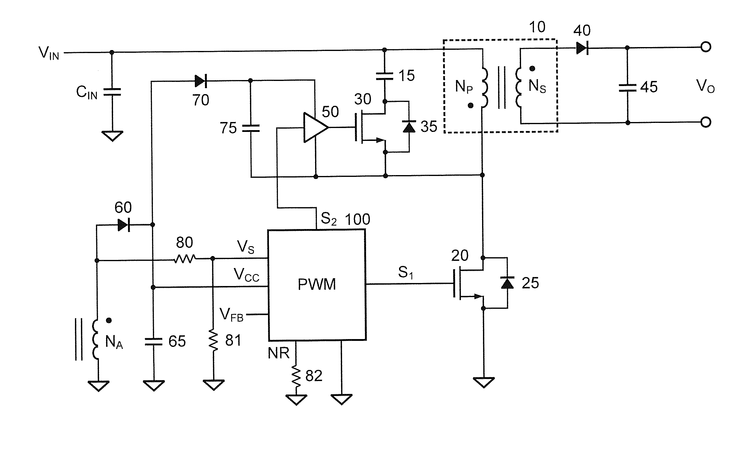
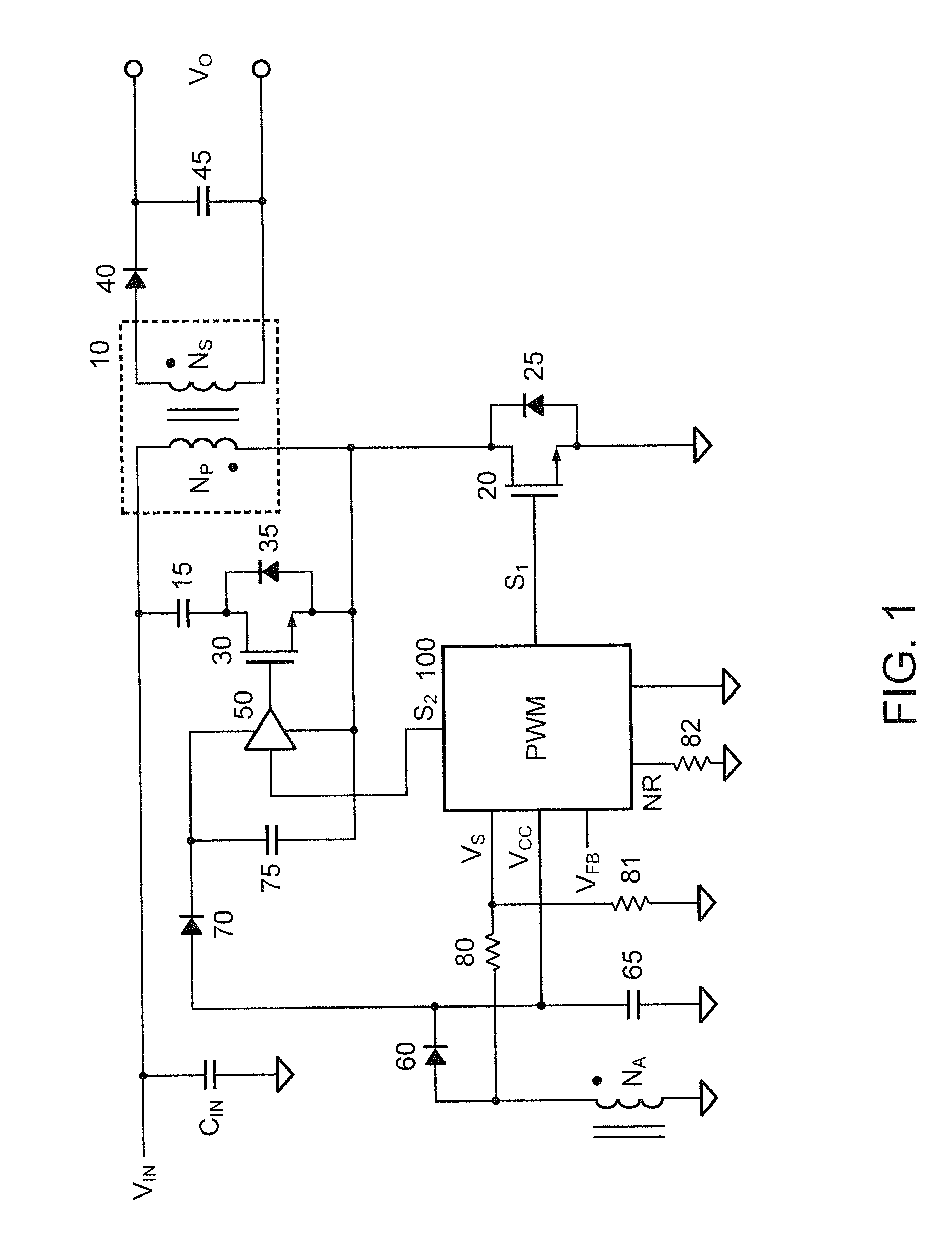
[0025]FIG. 1 is a circuit diagram of an embodiment of the power converter in accordance with the present invention. It is a flyback power converter with active clamp. The power converter includes a transformer 10 connected to an input voltage VIN of the power converter. The transformer 10 has a primary winding NP and a secondary winding NS. A first terminal of the primary winding NP is coupled to one terminal of an input capacitor CIN and receives the input voltage VIN. The other terminal of the input capacitor CIN is coupled to a ground. The control circuit for the flyback power converter includes transistors 20, 30, a capacitor 15, a high-side drive circuit 50, and a controller (PWM) 100.

[0026]The transistor 20 is coupled between a second terminal of the primary winding NP and the ground. The transistor 20 is a low-side transistor coupled to switch the primary winding NP of the transformer 10. A parasitic diode 25 is a body diode that is coupled to the transistor 20 in parallel. A...


PUM


Abstract

A control circuit of a flyback power converter according to the present invention comprises a low-side transistor, an active-clamper, a high-side drive circuit, and a controller. The low-side transistor is coupled to switch a transformer. The active-clamper is coupled in parallel with the transformer. The high-side drive circuit is coupled to drive the active-damper. The controller generates a switching signal and an active-clamp signal. The switching signal is coupled to drive the low-side transistor. The switching signal is generated in accordance with a feedback signal for regulating an output voltage of the flyback power converter. The active-clamp signal is coupled to control the high-side drive circuit and the active-clamper. The active-clamp signal is generated in response to a predicted time of the transformer. The predicted time is determined in accordance with an input voltage, the output voltage and an on time of the switching signal.

Description

BACKGROUND OF THE INVENTION[0001]1. Field of the Invention[0002]The present invention relates to power converter, and more particularly, relates to the control circuit of the flyback power converter with active clamp.[0003]2. Description of the Related Art[0004]The flyback power converter with active-clamp circuit has been developed to increase the efficiency of the flyback power converter. Nevertheless, the traditional active-clamp circuit can only achieve high efficiency for the heavy load. The drawback of the traditional active-clamp circuit is the higher power loss at the light load because of the high circulated current. The objective of this invention is to improve the efficiency of the flyback power converter by recycling the leakage inductance's energy of the transformer in the light load, and achieve the soft switching for the heavy load. Therefore, the flyback power converter can be operated at higher switching frequency for reducing the size of the transformer. The relate...

Claims


Application Information

Patent Timeline
Patent Type & Authority Applications(United States)
IPC IPC(8): H02M3/335
CPCH02M3/33507H02M3/33569Y02B70/10H02M1/342
Inventor YANG, TA-YUNG
Owner SEMICON COMPONENTS IND LLC
Why Eureka
Try Eureka