Inverter for grounded direct current source, more specifically for a photovoltaic generator

Inactive Publication Date: 2009-02-05
SMA SOLAR TECHNOLOGY
View PDF7 Cites 31 Cited by
  • Summary
  • Abstract
  • Description
  • Claims
  • Application Information

AI Technical Summary

Benefits of technology

[0017]The object of the invention is to provide an inverter by means of which capacitive leakage curre

Problems solved by technology

Through the low number of switches, switch losses are low but since the circuit needs absolutely symmetrical component parts such as chokes and capacitors, which is difficult in practical use, capacitive leakage currents can only be minimized but not completely avoided.
Another disadvantage is that it is not possible to directly ground the solar generator.
It is not possible to ground the generator with this circuit.
Direct grounding of the generator is also not possible.
Accordingly, between two switching processes and through asymmetries during switching, voltage differences form, which result in capacitive leakage currents.
One disadvantage is that the switches used are very much stressed because of the circuit array needed.
The disadvantage of this circuit is that the solar generator voltage is coupled directly to the intermediate circuit voltage.
Moreover, hard switching and intermediate magnetic storage of energy lead to high losses and large-sized passive components.
The use of only one switch for the two dual boost converters forcibly leads to higher load of said switch during switching operation.
This negat

Method used


Image

  • Inverter for grounded direct current source, more specifically for a photovoltaic generator
  • Inverter for grounded direct current source, more specifically for a photovoltaic generator
  • Inverter for grounded direct current source, more specifically for a photovoltaic generator

Examples


Example

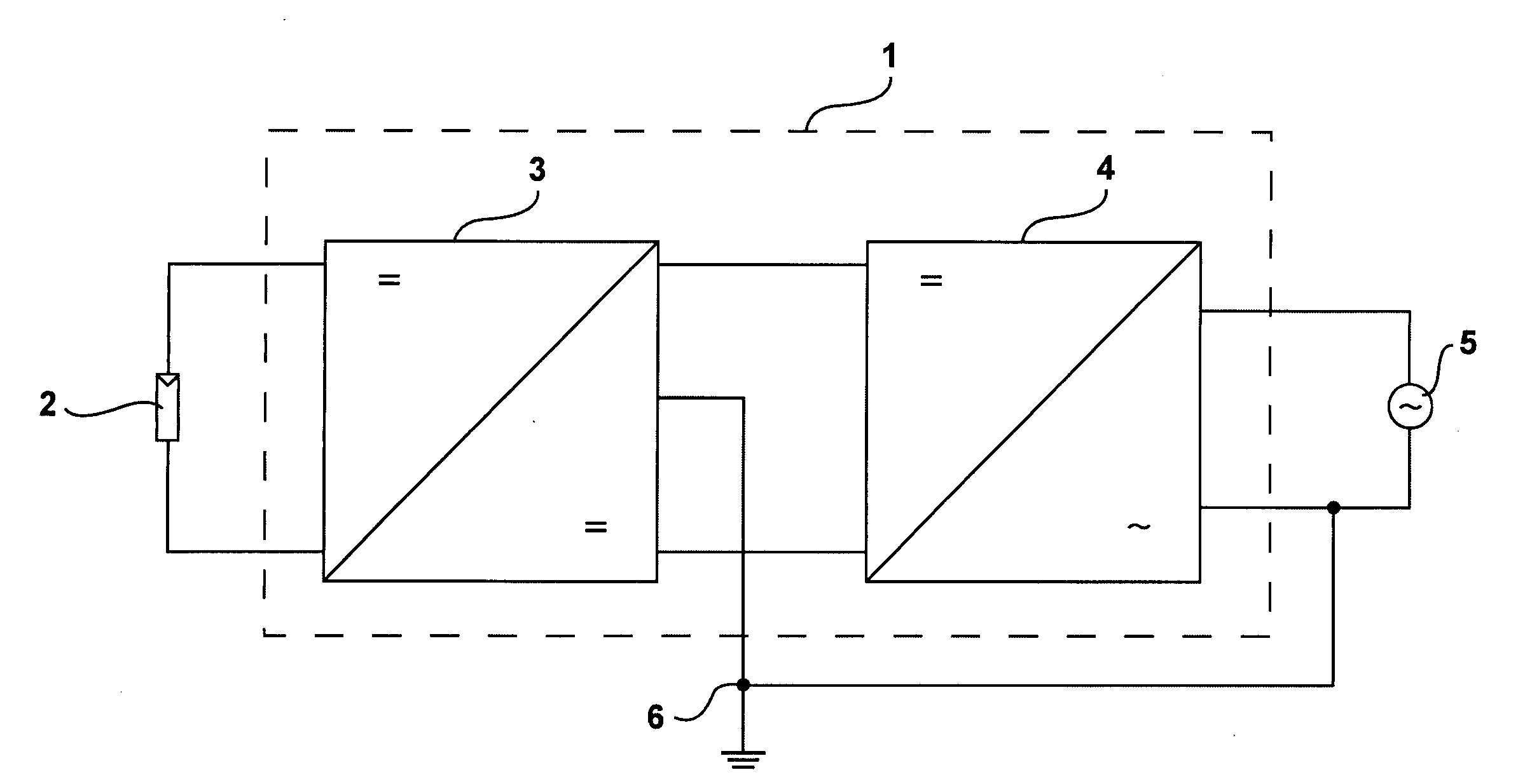
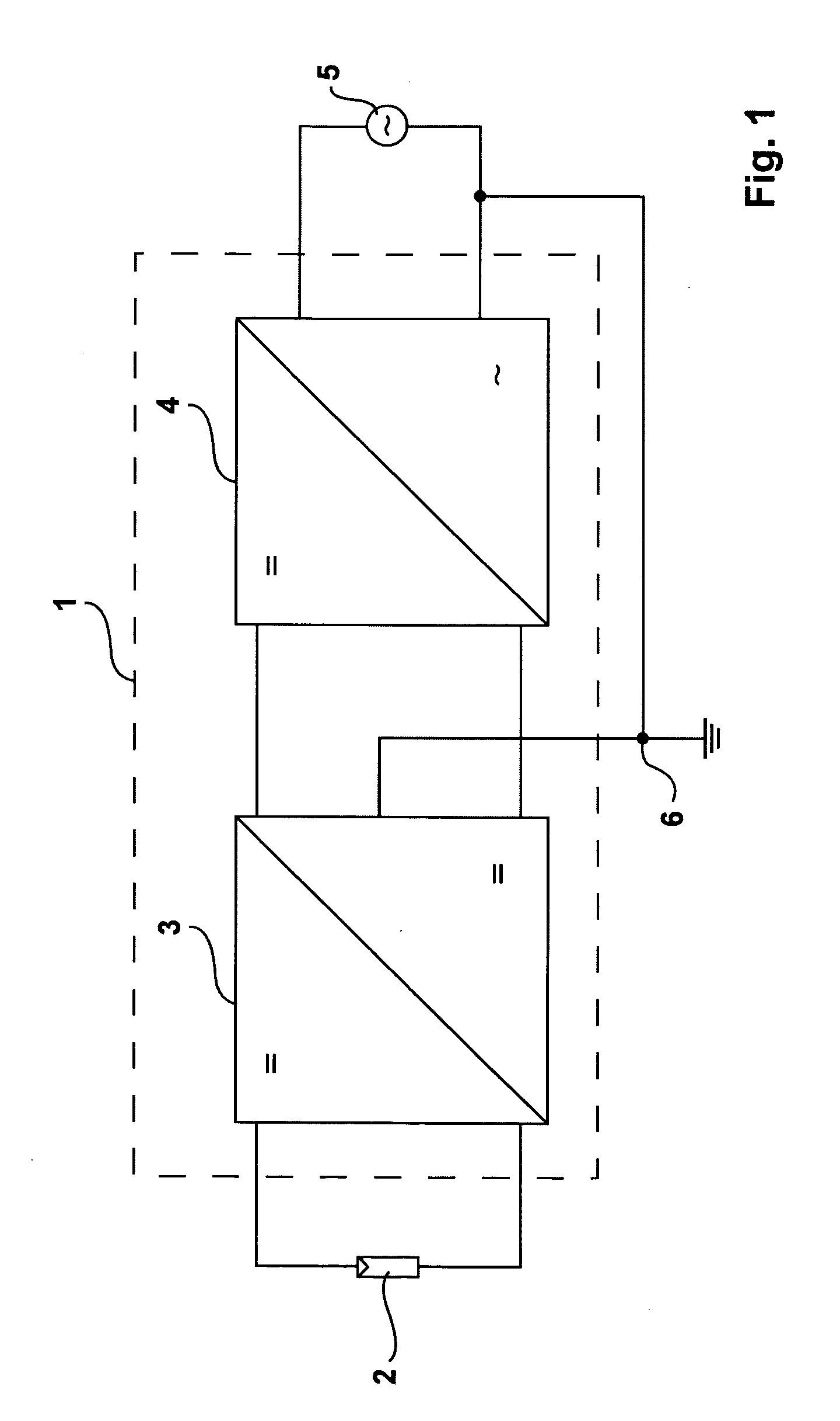
[0036]FIG. 1 shows a schematic diagram of the inverter 1 of the invention. A DC-DC converter 3 is connected downstream of a DC source, which is shown in FIG. 1 in the form of a photovoltaic generator 2. This DC-DC converter 3 supplies a DC-AC converter 4 the output of which is connected to a utility grid 5 and serves for feeding into said utility grid 5. The DC-DC converter 3 is thereby configured so as to allow for grounding both the DC source 2 and the grid 5 to a grounding point 6.

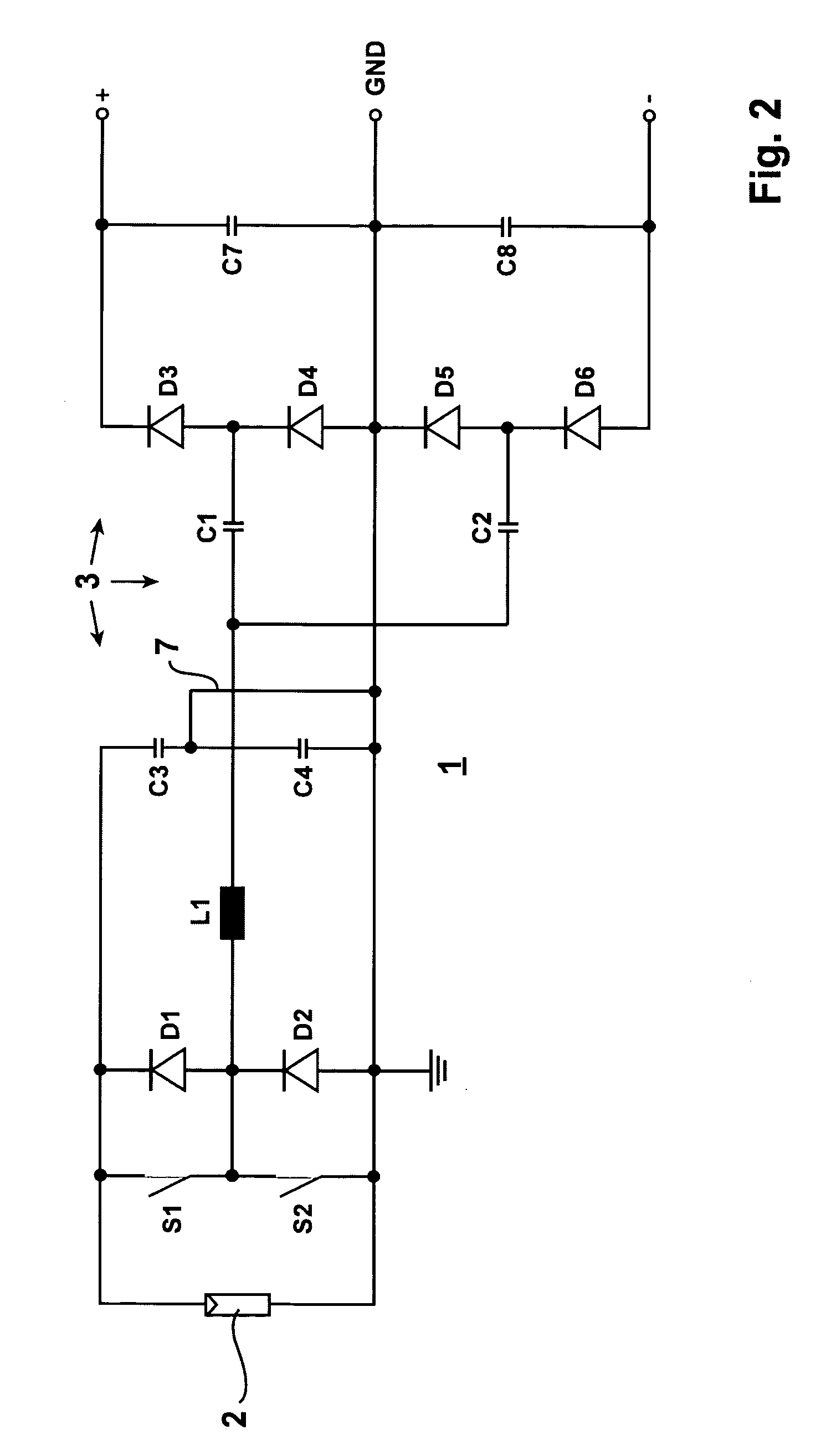
[0037]FIG. 2 shows a DC-DC converter 3 of the inverter 1 of the invention, which consists of the switches S1 and S2 with the respective anti-parallel diodes D1 and D2 which are switched on alternately, with the oscillating circuit inductivity L1, which can be implemented as a concentrated component part or as an assembled component part, with the two prorated oscillating circuit capacitors C1 and C2 as well as with the two rectifier branches. Each rectifier branch consists of two diodes. The first recti...


PUM


Abstract

An inverter (1) for a grounded direct voltage source, in particular for a photovoltaic generator (2), a battery or a fuel cell, for converting the direct voltage into an alternative voltage with a DC-DC converter (3) and a pulse inverter that is supplied by said DC-DC converter (3), said DC-DC converter (3) being configured to be an oscillating circuit inverter and comprising a series resonant oscillating circuit, said DC-DC converter (3), which is configured to be an oscillating circuit inverter, being configured to be a series-compensated oscillating circuit inverter with a choke (L1) and a series-mounted capacitor array consisting of two or several oscillating circuit capacitors, a rectifier bridge branch including 2 diodes (D3, D4; D5, D6, . . . ), being connected to each of the partial oscillating circuit capacitors, said rectifier bridge branch being connected with its positive or its negative pole to output side intermediate circuit capacitors which are preferably connected in series so that said DC-DC converter (3) delivers at least two bipolar output voltages and is combined with the pulse inverter (4) with a divided voltage intermediate circuit that is supplied from the oscillating circuit inverter.

Description

CROSS-REFERENCE TO RELATED APPLICATIONS[0001]This application claims Priority from German Application No. EP 07015324.2 filed on 4 Aug. 2007FIELD OF THE INVENTION[0002]The invention relates to an inverter for a grounded direct voltage source, in particular for a photovoltaic generator, a battery or a fuel cell, for converting the direct voltage into an alternating voltage with a DC-DC converter and a pulse inverter supplied by the DC-DC converter.[0003]Unavoidable parasitic capacitances occur on photovoltaic generators. If high-frequency clocked pulse inverters are being utilized for converting the generator's direct current into an alternating voltage at mains frequency, considerable, in parts not tolerable AC leakage currents can flow to ground from the photovoltaic generator.[0004]Great potential jumps at mains frequency can also lead to AC leakage currents because of their steep increase in voltage.DESCRIPTION OF THE PRIOR ART[0005]From the document DE 10 2004 037 446 A1 a trans...

Claims


Application Information

Patent Timeline
IPC IPC(8): H02M7/48
CPCH02M3/158H02M2001/007H02J3/383Y02B70/1425Y02E10/563H02M2001/009H02J2300/24H02J3/381Y02B70/10Y02E10/56H02M1/009H02M1/007H02M7/05H02M7/48H02J7/35
Inventor ENGEL, BERNDMALLWITZ, REGINEZACHARIAS, PETER
Owner SMA SOLAR TECHNOLOGY
Why Eureka
Try Eureka