Carrier plate for a punching tool

Inactive Publication Date: 2010-06-24
KARL MARBACK
View PDF6 Cites 0 Cited by
  • Summary
  • Abstract
  • Description
  • Claims
  • Application Information

AI Technical Summary

Benefits of technology

[0017]Thus the carrier plate according to the invention can be manufactured at relatively little expense, and yet it has all the required properties. Among those are a high dimensional stability even after a large number of punching operations, a low absorption of humidity, a good cutting rule mountability, a high rigidity and compression load capacity

Problems solved by technology

A disadvantage of the carrier plate disclosed in DE 203 20 658 U1 is the use of non-recyclable epoxy resins in the middle layer of the carrier plate.
In addition, the materials used are relatively cost-intensive to manufacture.
A disadvantage of such carrier plates is that the recycling of epoxy resins is problema

Method used


Image

  • Carrier plate for a punching tool
  • Carrier plate for a punching tool
  • Carrier plate for a punching tool

Examples


Example

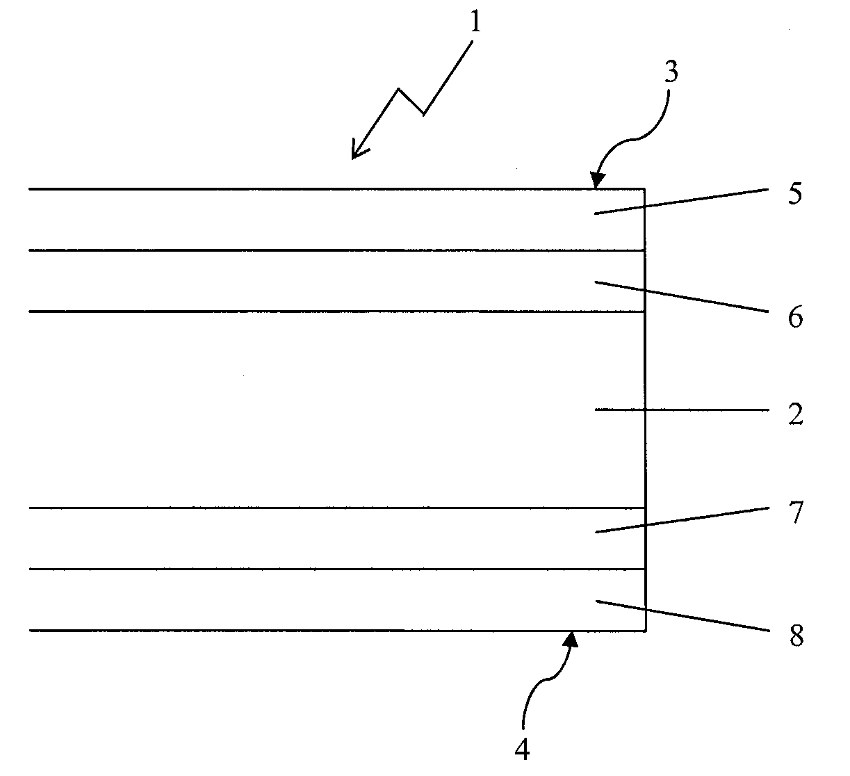
[0022]The carrier plate 1 shown in FIG. 1 has three layers: a middle layer 2 consisting of a plate-shaped MDF wood fiber core and two external layers 3, 4, each of which is formed by two crosswise glued plies 5, 6 and 7,8, respectively, made of birch veneer which is as defect-free and even as possible. The middle layer 2 and the external layers 3, 4 have been glued together by means of a urea glue using pressure and heat, wherein the external layers 3, 4 are glued together cross-wise.

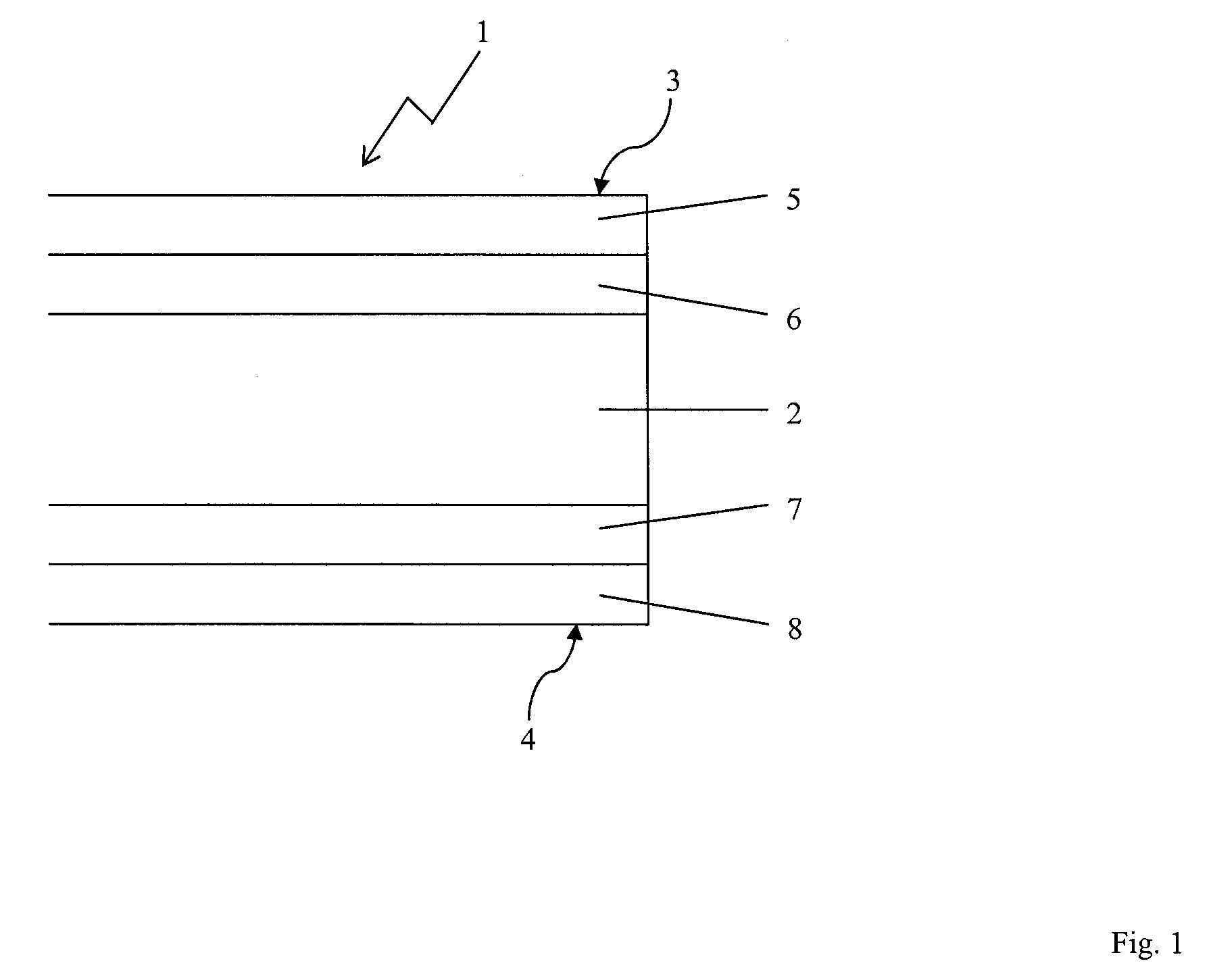
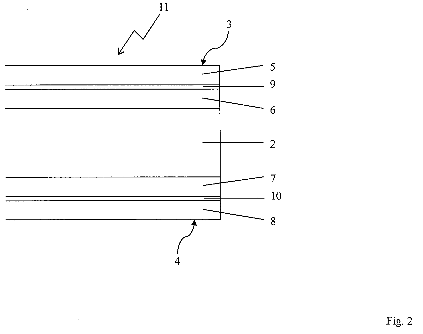
[0023]The carrier plate 11 shown in FIG. 2 differs from the carrier plate 1 shown in FIG. 1 in that between the two plies of birch veneer 5, 6 and 7, 8, respectively, there is a reinforcement 9, 10 made of glass fiber fabric having a mesh width of 1.7 mm and a thickness of 0.3 mm, which reinforcement has been treated with a chromium or silane sizing agent having a thickness of 1 μm. Thereinafter the two plies of birch veneer 5, 6 and 7, 8, respectively, are glued together crosswise with the reinforcemen...


PUM

PropertyMeasurementUnit
Lengthaaaaaaaaaa
Lengthaaaaaaaaaa
Fractionaaaaaaaaaa

Abstract

A carrier plate (1) for a punching tool includes two external layers (3,4), between which a middle layer (2) is arranged, wherein the middle layer (2) is formed by a core made of compacted fibers and the external layers (3, 4) are formed by wood veneer.

Description

FIELD OF THE INVENTION [0001]The invention relates to a carrier plate for a punching tool having two external layers, between which a middle layer is arranged.DESCRIPTION OF THE BACKGROUND ART [0002]DE 203 20 658 U1 discloses a carrier plate for a punching tool having at least two layers. The middle layer of this carrier plate preferably consists of a foamed plastic, especially epoxy resin. The external layer consists of a compound material made of artificial resin and glass fabric or made of metal.[0003]A disadvantage of the carrier plate disclosed in DE 203 20 658 U1 is the use of non-recyclable epoxy resins in the middle layer of the carrier plate. In addition, the materials used are relatively cost-intensive to manufacture.[0004]Furthermore, it is known to use so-called composite plates as carrier plates in the construction of punch dies. These consist, for example, of a compound made of sheet metal / wood / sheet metal, sheet metal / plastics / sheet metal or sheet metal / sisal, resin / s...

Claims


Application Information

Patent Timeline
IPC IPC(8): B32B5/12B32B21/14B32B15/10B32B17/02B32B7/02B32B21/02B32B21/04
CPCB26D2007/2607B26F1/40Y10T428/24967B26F2001/4463Y10T428/24066B26F1/44Y10T428/249921Y10T428/31703Y10T428/31804Y10T428/31982
Inventor MARBACH, PETER
Owner KARL MARBACK
Why Eureka
Try Eureka