Equipment and method for testing Young modulus and consumption factor of loudspeaker cone

A Young's modulus and loss factor technology, which is applied to the Young's modulus and loss factor testing equipment and testing field of speaker cones, can solve the problem of low accuracy of Young's modulus and loss factor.

Inactive Publication Date: 2012-11-28
广州市拓煌电声配件科技有限公司 +1
View PDF3 Cites 8 Cited by
  • Summary
  • Abstract
  • Description
  • Claims
  • Application Information

AI Technical Summary

Problems solved by technology

[0060] The above-mentioned structure, because of the three-dimensional automatic guide rail system is set, so that the displacement sensor can test the continuous multiple test points of the speaker cone sample from the top to the root, and under the action of the rotating drive device, the displacement sensor can find the The vertical position of each test point, so that the movement trajectory of the displacement sensor is always consistent with the curvature of the cone. The test results of multiple consecutive points are finally averaged into the average Young's modulus and loss factor of the cone. This solves the test The Young’s modulus and loss factor accuracy of the cone sample with bending radian and uneven thickness are not high. At the same time, at the same test point, the displacement sensor is controlled by the processor to continuously scan the given frequency range. In this way, a smooth and accurate amplitude-frequency curve can be obtained. Therefore, by finding the vertical position to the test point and continuously scanning the frequency, the accuracy of the Young's modulus and loss factor of the test basin sample can be improved.

Method used


Image

  • Equipment and method for testing Young modulus and consumption factor of loudspeaker cone
  • Equipment and method for testing Young modulus and consumption factor of loudspeaker cone
  • Equipment and method for testing Young modulus and consumption factor of loudspeaker cone

Examples


Embodiment Construction

[0087] The present invention will be further described in detail below in conjunction with the accompanying drawings and specific embodiments.

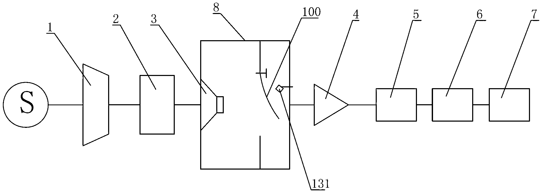
[0088] Speaker cone Young's modulus and loss factor testing equipment includes excitation sound wave generator, vibration device, cone sample fixture, three-dimensional automatic guide rail system, non-contact laser vibration pickup device, processor 6, control cabinet and control panel 7.

[0089] Described excitation sound wave generating device comprises signal generator 1, power amplifier 2 and loudspeaker 3, and signal generator 1 produces sinusoidal signal as excitation source, and the generation of sinusoidal signal and frequency band are controlled by processor 6, and after sinusoidal signal produces, through power amplifier 2 After being amplified, it is input into the speaker 3, and the speaker 3 generates sound pressure.

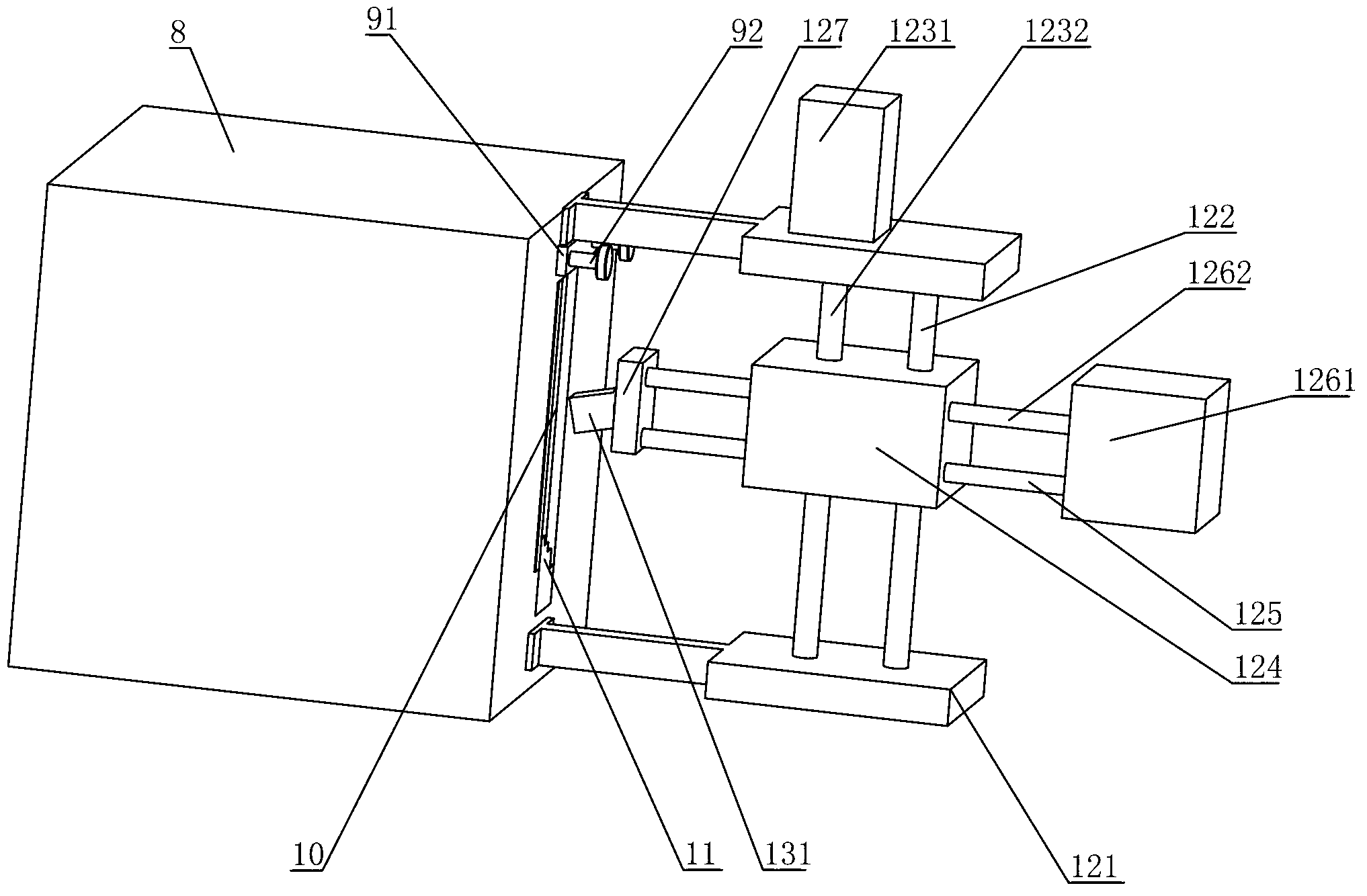
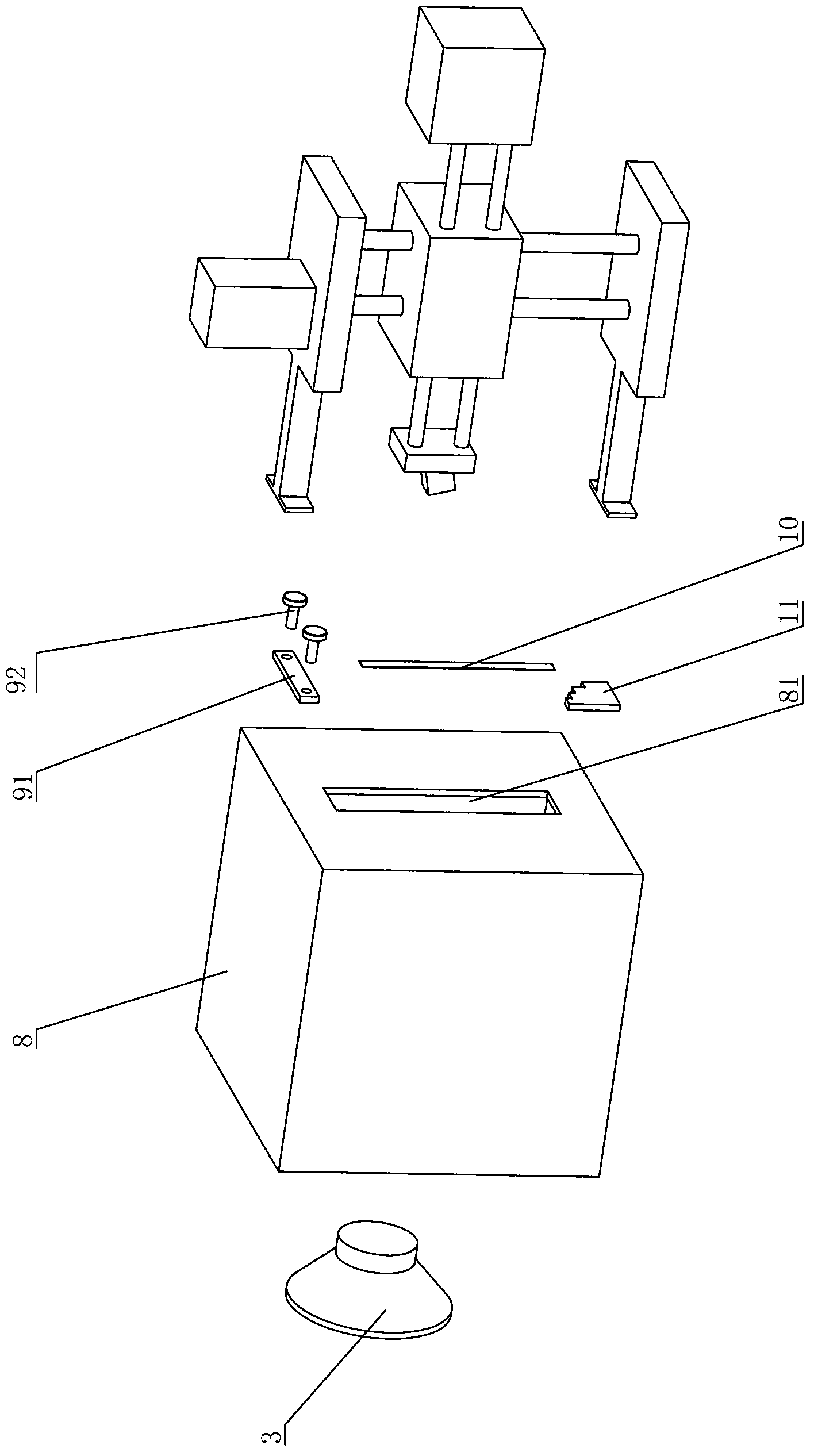
[0090] Such as image 3 and Figure 4 As shown, the excitation device is a box body 8 on which a sp...


PUM


Abstract

The invention discloses equipment and method for testing a Young modulus and a consumption factor of a loudspeaker cone. The testing equipment comprises a motivation acoustic wave generating device, a shock excitation device, a cone test sample clamp, a three-dimensional automatic guide rail system, a non-contact laser vibration pick-up device, and a processor. The testing method comprises the following steps that: a cone testing sample is clamped for searching a test point by means that a displacement sensor automatically searches a vertical distance position of the point by rotating a driving device; the motivation acoustic wave generating device generates acoustic pressure, so as to enable the cone testing sample to generate simple harmonic vibration through the shock excitation device; the displacement sensor continuously scans all frequencies of a given frequency band at the point, so as to form an analogue electric signal; and the analogue electric signal is subjected to amplification conversion, so that the Young modulus and the consumption factor can be calculated through the processor. With the adoption of the testing equipment and the testing method provided by the invention, the precision of testing the Young modulus and the consumption factor is high.

Description

technical field [0001] The invention relates to a testing device and a testing method for testing the Young's modulus and loss factor of the loudspeaker cone. Background technique [0002] Young's modulus is an extremely important physical quantity in solid materials. It reflects the anti-deformation ability of an object when it is subjected to external force on a macroscopic level. It is an indispensable physical quantity in mechanical calculations; it can reflect the structure of a material on a microscopic level. Therefore, Young's modulus The determination of quantity has always been valued by people. Generally speaking, there are two methods for determining Young's modulus, namely: static measurement method and dynamic measurement method. The static method is usually used for large deformation and normal temperature. Its disadvantage is due to The load is large, the loading speed is slow, and there is a relaxation process, which cannot truly reflect the change of the in...

Claims


Application Information

Patent Timeline
Patent Type & Authority Applications(China)
IPC IPC(8): H04R29/00
Inventor 梁乃忠王立世陈港
Owner 广州市拓煌电声配件科技有限公司
Why Eureka
Try Eureka