
LED lighting lens

An LED lighting and lens technology, applied in lighting devices, lighting and heating equipment, components of lighting devices, etc., can solve the problems of low efficiency of lamps, complicated installation and positioning, etc., and achieve the effect of improving the efficiency of lamps

Inactive Publication Date: 2012-12-05
SUZHOU SIMURG OPTOELECTRONICS
View PDF0 Cites 3 Cited by
  • Summary
  • Abstract
  • Description
  • Claims
  • Application Information

AI Technical Summary

Problems solved by technology

[0003] In order to solve the problems of low lamp efficiency and complicated installation and positioning in the existing technical solutions, the present invention provides the following technical solutions:

Method used


Image

  • LED lighting lens
  • LED lighting lens

Examples


Embodiment Construction

[0019] The process embodiment will be described in detail below, so that the advantages and features of the present invention can be more easily understood by those skilled in the art, so as to define the protection scope of the present invention more clearly.

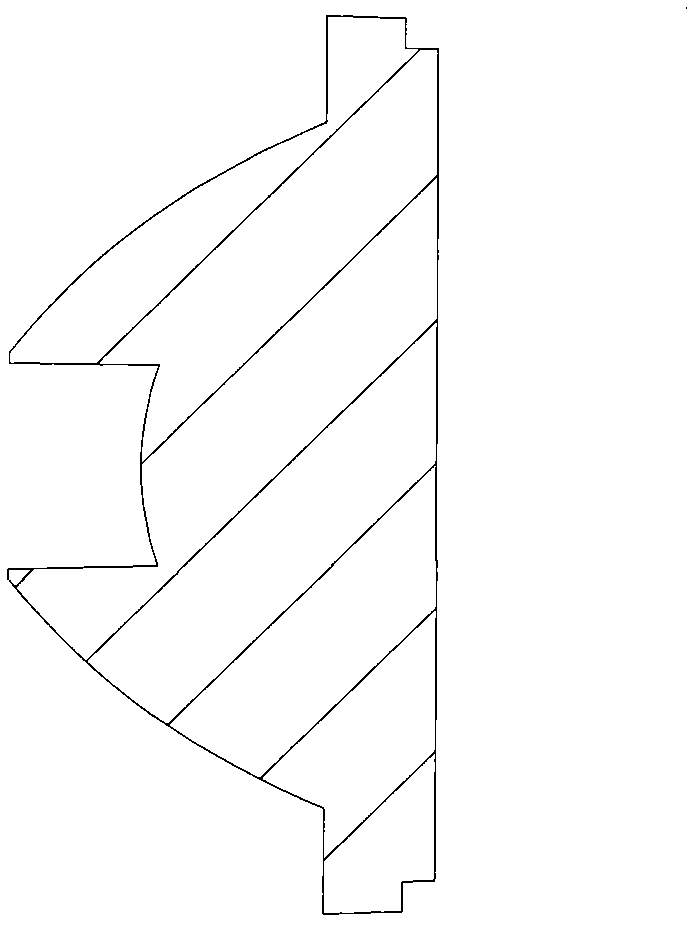
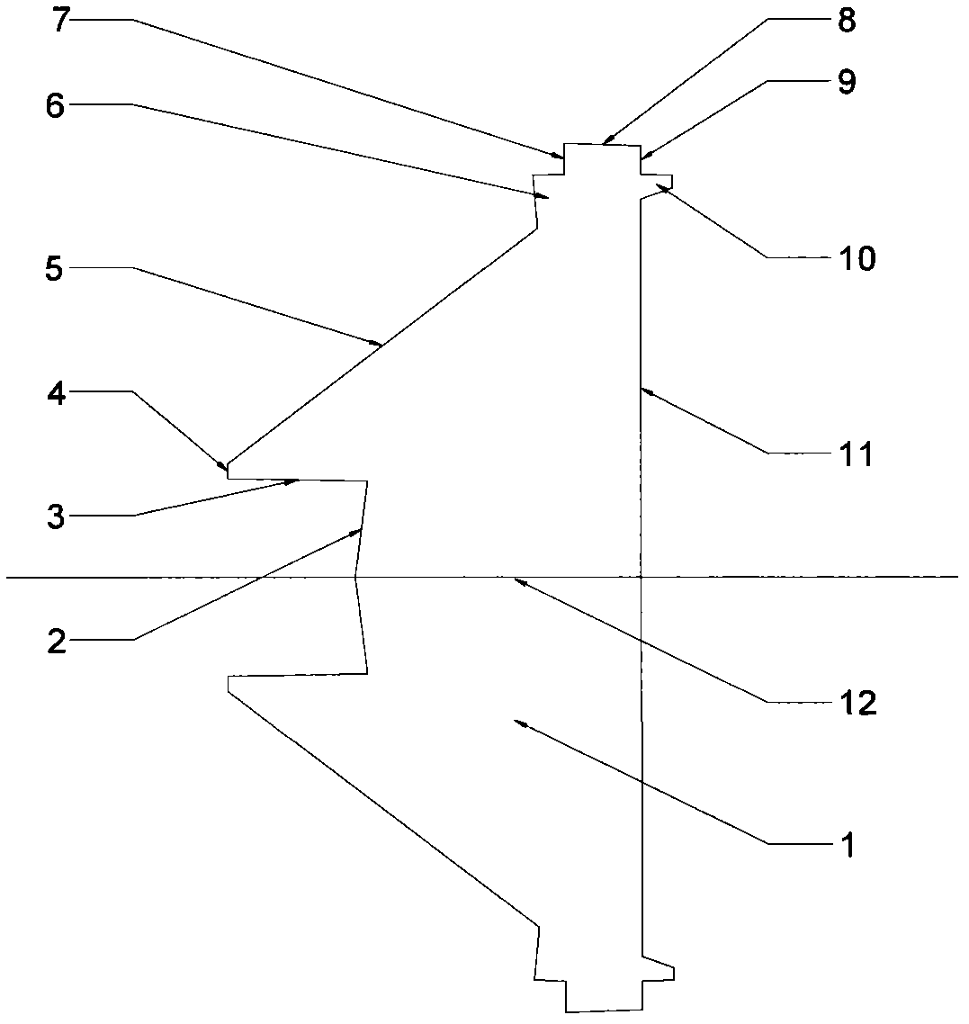
[0020] Such as figure 2 As shown in the sectional view of the rotating central axis of the present invention, an LED lighting lens includes a body 1 that is a rotating body. On one side of the body 1, there are refraction surface 2, draft cone surface 3, and LED stickers in sequence from the center to the periphery. The joint surface 4, the total reflection surface 5, the negative clamping surface 7 and the outermost glue-in surface 8, on the other side of the body 1 are the middle light-emitting plane 11 and the positive clamping surface 9 located on the periphery of the light-emitting plane 11, with the body 1 The central axis 12 is the X-axis, the side of the light-emitting plane 11 is the positive direction, and a...


PUM


Abstract

The invention relates to a lens used in the field of LED lighting. The lens comprises a rotary body. A refraction side, a draft conical side, an LED fitting side, a full reflection side, a negative clamp side and an outermost adhesive inlet side are sequentially arranged on one side of the body from the center to the outer periphery. A light outlet plane in the middle and a positive clamp side arranged on the periphery of the light outlet plane are arranged on the other side of the body. A planar coordinate system with a millimeter as a unit is set by utilizing the central axis of the body as an X axis, considering one side of the light outlet plane as the positive direction and utilizing any one of straight lines penetrating through the center of the light outlet plane as a Y axis. The rotary generatrix of the body penetrates through a specific area of the coordinate system when rotating. A negative limit boss is arranged between the full reflection side and the negative clamp side, and a positive limit boss is arranged between the positive clamp side and the light outlet plane. By the lens, efficiency of LED lamps is improved, lighting can be uniformly circularly distributed, and no rainbow color area is caused.

Description

technical field [0001] The invention relates to the field of semiconductor lighting, in particular to a non-imaging lens of PMMA material used in LED lighting. Background technique [0002] As a new type of environment-friendly light source, LED is being more and more widely used in TV backlight, general lighting, and vehicle lighting. At present, in the semiconductor lighting industry that has just emerged in the past two years, lighting optical lens products peers mostly use modeling, simulation and repeated design methods. The product design results are too random, and mainly produce lighting lenses that converge light spots. Such lenses can Produces a lighting effect in which the illuminance is high in a small area in the center of the lighting surface and the illuminance decreases to the surroundings. In addition, there are also a small number of companies that use imaging theory to design and produce convex or concave lenses. Although they can also produce lighting ef...

Claims


Application Information

Patent Timeline
Patent Type & Authority Applications(China)
IPC IPC(8): F21V5/04F21Y101/02
Inventor 独育飞刘建敏
Owner SUZHOU SIMURG OPTOELECTRONICS
Learn More