Light emitting device and composite lens thereof

A light-emitting device and composite lens technology, which is applied in the direction of lighting devices, components of lighting devices, cooling/heating devices of lighting devices, etc., can solve the problems that the light distribution angle cannot be achieved, and achieve the effect of improving the light output angle

Inactive Publication Date: 2012-12-05
AETHER SYST
View PDF2 Cites 12 Cited by
  • Summary
  • Abstract
  • Description
  • Claims
  • Application Information

AI Technical Summary

Problems solved by technology

However, since the light emitted by the LED 11 is directional and needs to be installed on the base to facilitate heat dissipation, the light irradia

Method used


Image

  • Light emitting device and composite lens thereof
  • Light emitting device and composite lens thereof
  • Light emitting device and composite lens thereof

Examples


Example Embodiment

[0056] Hereinafter, a light-emitting device and a compound lens according to a preferred embodiment of the present invention will be described with reference to related drawings, wherein the same elements will be described with the same element symbols.

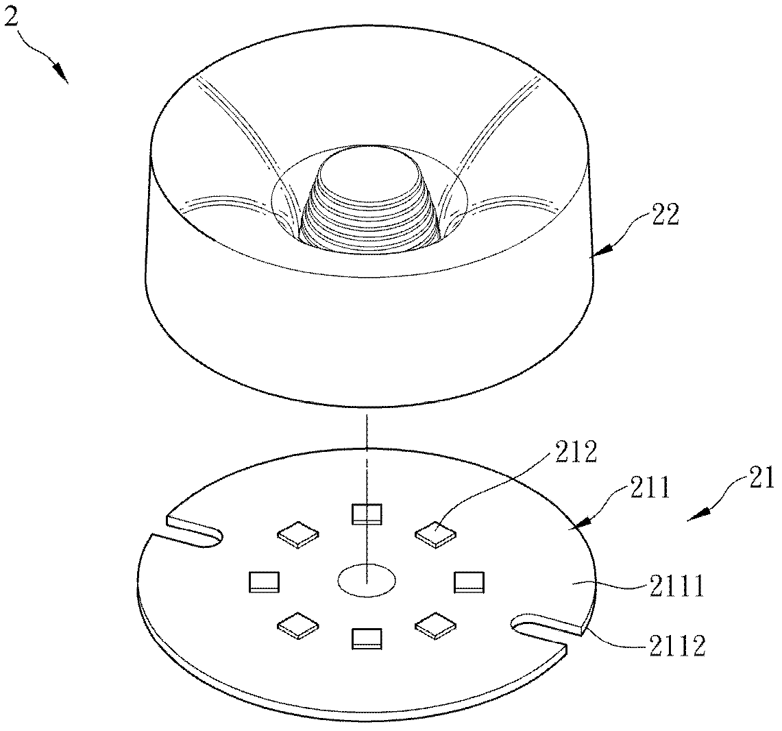
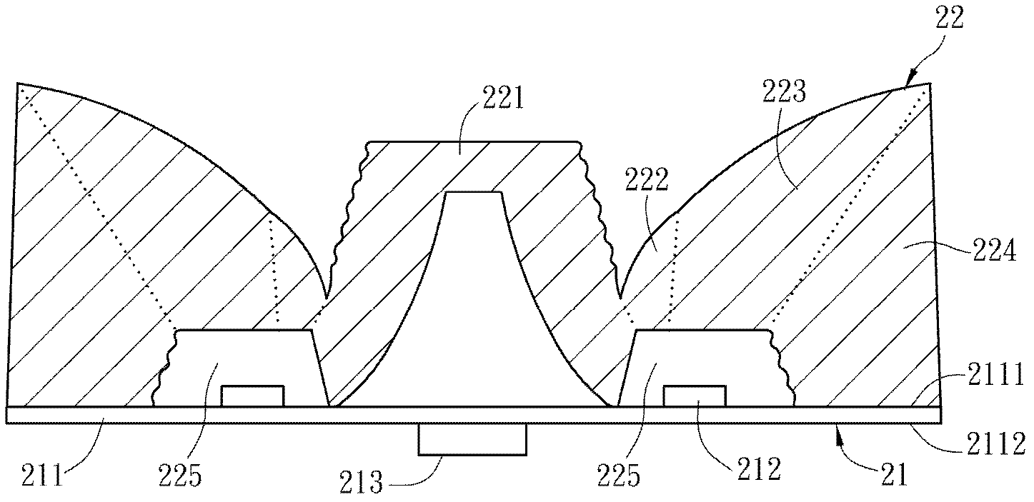
[0057] First, please refer to Figure 2A and Figure 2B , Respectively are a schematic diagram and a cross-sectional view of a light emitting device 2 according to a preferred embodiment of the present invention. The light emitting device 2 includes a light emitting module 21 and a compound lens 22.

[0058] In this embodiment, the light emitting module 21 has a substrate 211, eight light emitting diodes 212 and a driving circuit 213. Here, the substrate 211 may be a circuit board, and the light emitting diode 212 is mounted on a surface 2111 of the substrate 211 in a ring-shaped arrangement. In application, in order to reduce the volume of the light emitting module 21, the light emitting diode 212 may be a chip type light emitti...


PUM


Abstract

A light emitting device comprises a light emitting module and a composite lens. The composite lens is arranged above the light emitting module, and the light emitting module includes a first lens unit, a second lens unit, a third lens unit and a fourth lens unit. The first lens unit radiates a first group of lights, which are emitted by the light emitting module, outward from the first lens unit in a total reflection way. The second lens unit radiates a second group of lights, which are emitted by the light emitting module, through the third lens unit and outward from the fourth lens unit in a total reflection way. The third lens unit radiates a third group of lights, which are emitted by the light emitting module, outward from the fourth lens unit in a total reflection way. The fourth lens unit radiates a fourth group of lights, which are emitted by the light emitting module, outward from the fourth lens unit in a total reflection way. Thus, the light emitting angle is improved, thereby providing a light emitting device with high angle light distribution. Besides, the invention also discloses a composite lens.

Description

technical field [0001] The present invention relates to a light-emitting device and its compound lens, in particular to a light-emitting device with a light-emitting diode as a light source and its compound lens. Background technique [0002] In recent years, due to the continuous improvement of the process and materials of light emitting diodes (LEDs), the luminous efficiency of light emitting diodes has been greatly improved. Different from ordinary fluorescent lamps or energy-saving light bulbs, light-emitting diodes have the characteristics of low power consumption, long service life, high safety, short luminous response time and small size. Therefore, light-emitting diodes have been widely used in many types of electronic products . One of the applications is to use light-emitting diodes as light bulbs to replace traditional fluorescent tubes and fluorescent bulbs. [0003] Please refer to figure 1 As shown, the known LED lamp 1 has an LED 11 and a circuit board 12 ....

Claims


Application Information

Patent Timeline
IPC IPC(8): F21V5/04F21V23/00F21V17/00F21V29/00F21Y101/02
Inventor 周彦均
Owner AETHER SYST
Why Eureka
Try Eureka