Stroboscopic optical image mapping system

An optical image, stroboscopic technology, applied in the field of optical systems, can solve problems such as high cost

Inactive Publication Date: 2015-06-24
陈亮嘉 +1
View PDF5 Cites 0 Cited by
  • Summary
  • Abstract
  • Description
  • Claims
  • Application Information

AI Technical Summary

Problems solved by technology

However, the optical image imaging system 1 requires fast data acquisition speed in hardware, so the cost remains high

Method used


Image

  • Stroboscopic optical image mapping system
  • Stroboscopic optical image mapping system
  • Stroboscopic optical image mapping system

Examples


Embodiment Construction

[0063] In order to enable the examiner to have a further understanding of the features, purpose and functions of the present invention, the relevant detailed structure and design concept of the device of the present invention will be explained below, so that the examiner can understand the characteristics of the present invention , the detailed statement is as follows:

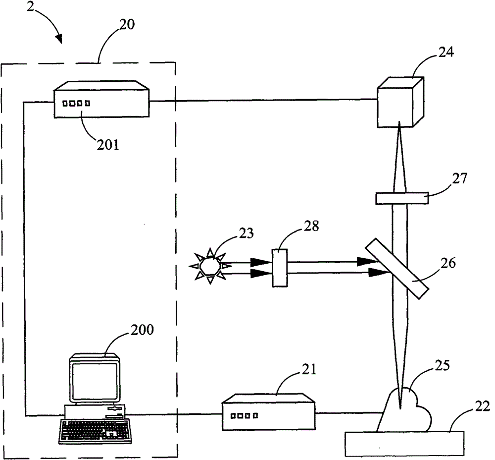
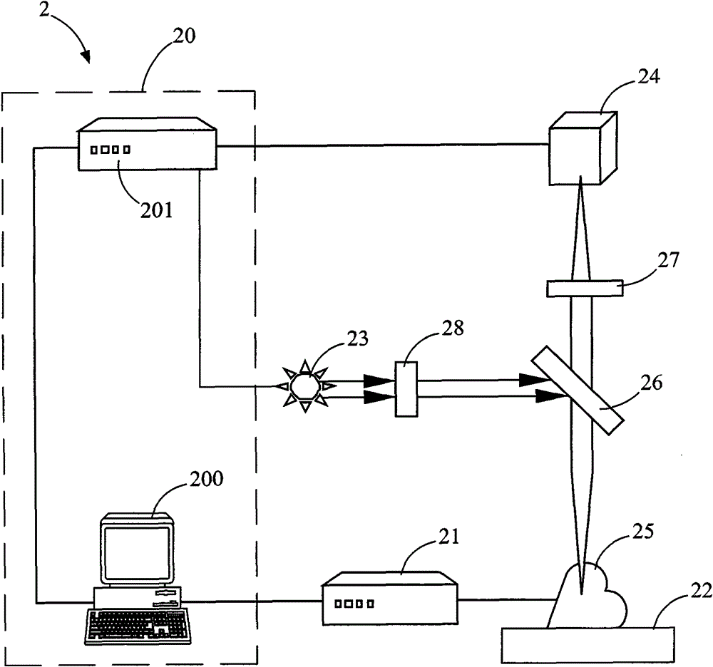
[0064] see Figure 2A As shown, this figure is a schematic diagram of the structure of the first embodiment of the stroboscopic optical image imaging system of the present invention. In this embodiment, the stroboscopic optical image imaging system 2 includes a control module 20 , a signal generating device 21 , a carrying platform 22 , a light source module 23 and an image capture unit 24 . The control module 20 performs delay control on a first pulse signal to form a delayed pulse signal. see Figure 3A As shown, the figure is a schematic diagram of the first pulse signal. The first pulse signal 90 has a...


PUM


Abstract

The invention provides a stroboscopic optical image mapping system which comprises a control module, a light source module and an image acquisition unit. The control module actuates a delay control to a first pulse signal which has a cycle and consists of a plurality of pulses, so that a delayed pulse signal is formed. The time interval of adjacent pulses of the delayed pulse signal and the cycle are provided with a time difference. The light source provides an incident beam irradiating an organization containing dye. The organization generates a continuous action level signal by the aid of a second pulse signal. The incident beam triggers the dye in the organization to generate a fluorescent beam as intense as the continuous action level signal. The image acquisition unit acquires the fluorescent beam to generate a plurality of fluorescent images according to the delayed pulse signal.

Description

technical field [0001] The invention relates to an optical system, in particular to a stroboscopic optical image imaging system utilizing stroboscopic technology. Background technique [0002] Cells (excitable cells; such as nerve cells or cardiomyocytes, etc.) that can generate excitable potentials in organisms produce changes in the potential difference between the inside and outside of the cells through the permeation of ions on the cell membrane, which is an important function to maintain the normal physiology of these cells. Cells that can generate excitatory potentials are responsible for the transmission of intercellular information (cell-cell communication) and the initiation of excitatory potentials (triggering action potential). The science of studying the physiological changes of organisms caused by changes in cell membrane potentials or tissue action potentials is called electrophysiology; if it is limited to heart cells or tissues, it is called electrophysiology...

Claims


Application Information

Patent Timeline
Patent Type & Authority Patents(China)
IPC IPC(8): G01N21/64
Inventor 陈亮嘉赖宇俊张伟伦叶宏一
Owner 陈亮嘉
Why Eureka
Try Eureka