Reconfigurable circuit to emulate system critical paths

a reconfigurable circuit and critical path technology, applied in the field of microprocessors, can solve problems such as the failure of the microprocessor operation

Inactive Publication Date: 2015-02-12
GLOBALFOUNDRIES INC
View PDF2 Cites 10 Cited by
  • Summary
  • Abstract
  • Description
  • Claims
  • Application Information

AI Technical Summary

Benefits of technology

[0006]According to one exemplary embodiment, a circuit for monitoring and controlling a clock signal generated by a clock source in a microprocessor device may include a voltage divider network that provides a plurality of voltages, a selector device that receives the plurality of voltages and provides a scaled supply voltage and a scaled ground voltage selectable from the received plurality of voltages, and at least one delay element that receives the scaled supply voltage and the scaled ground voltage and generates a delayed pulse signal by applying a delay to each pulse of the clock signal. The delayed pulse signal may include a delay magnitude that is controllable by the scaled supply voltage and the scaled ground voltage, such that the delayed pulse signal is used to generate a frequency correction signal based on a variation to a supply voltage of the microprocessor. The frequency correction signal may then be applied to the clock source for maintaining a frequency guardband for the clock signal of the mic

Problems solved by technology

Therefore, as a result of driving the microprocessor at a nominal frequency (i.e., 4.5 GHz) that i

Method used


Image

  • Reconfigurable circuit to emulate system critical paths
  • Reconfigurable circuit to emulate system critical paths
  • Reconfigurable circuit to emulate system critical paths

Examples


Embodiment Construction

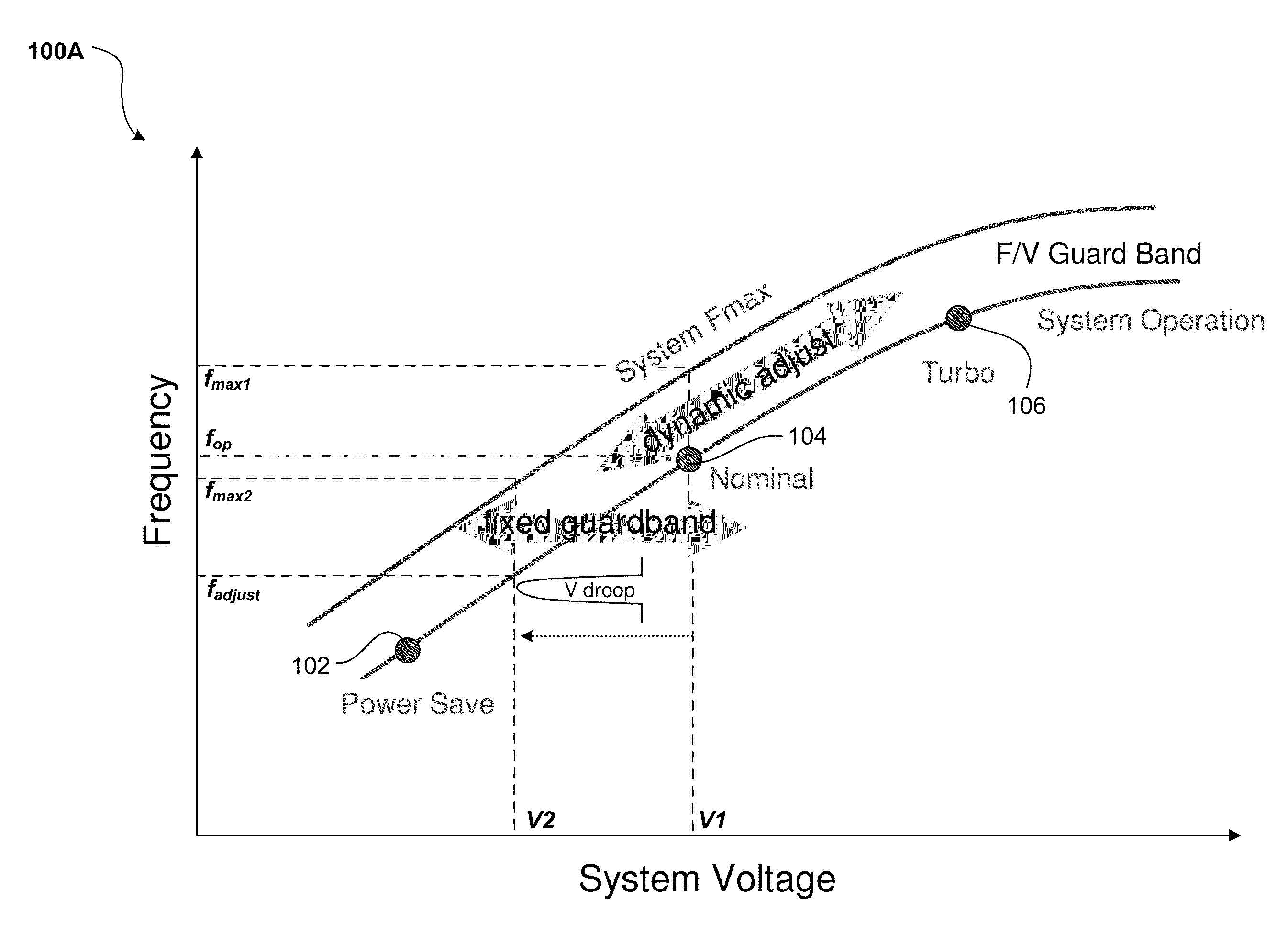
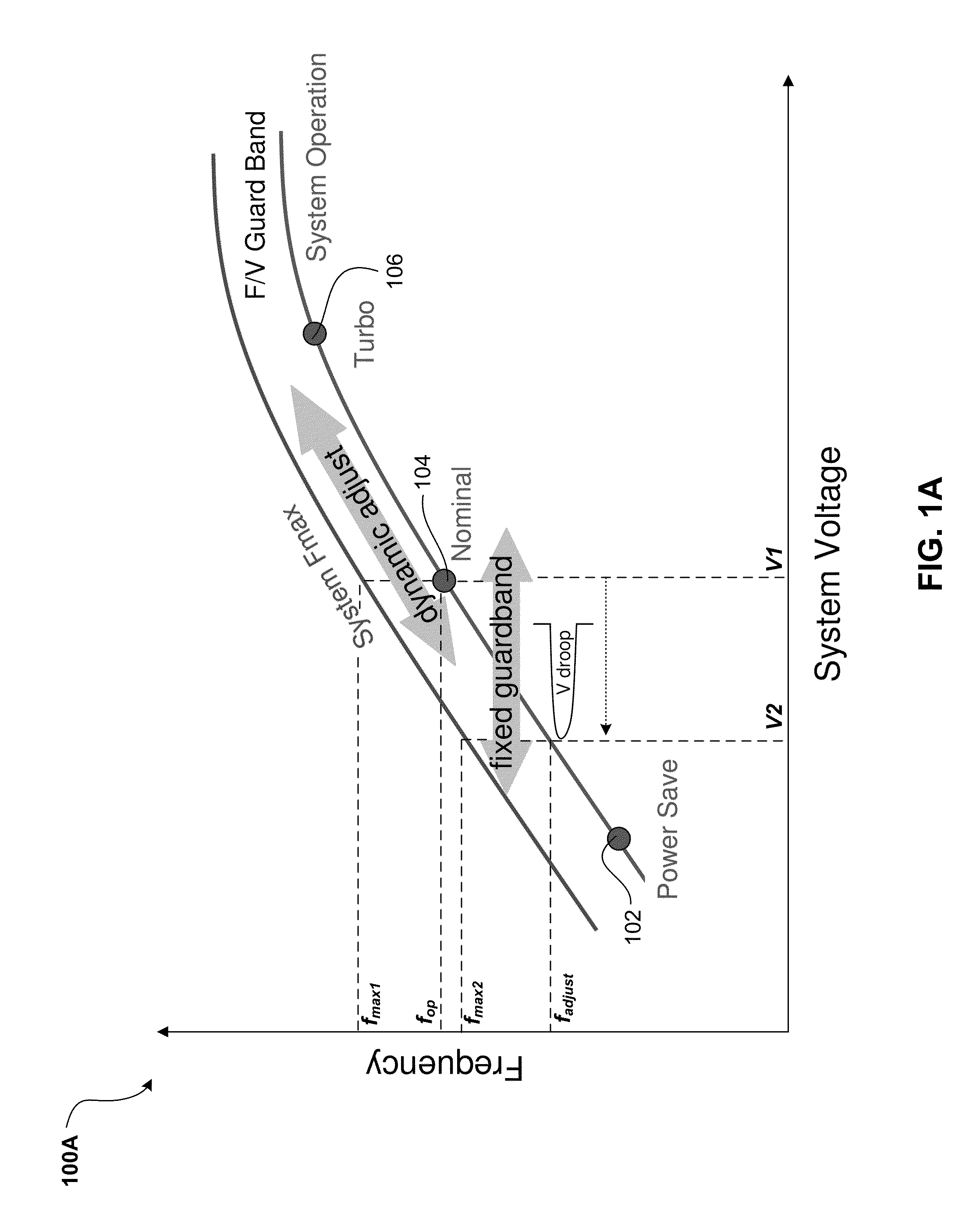
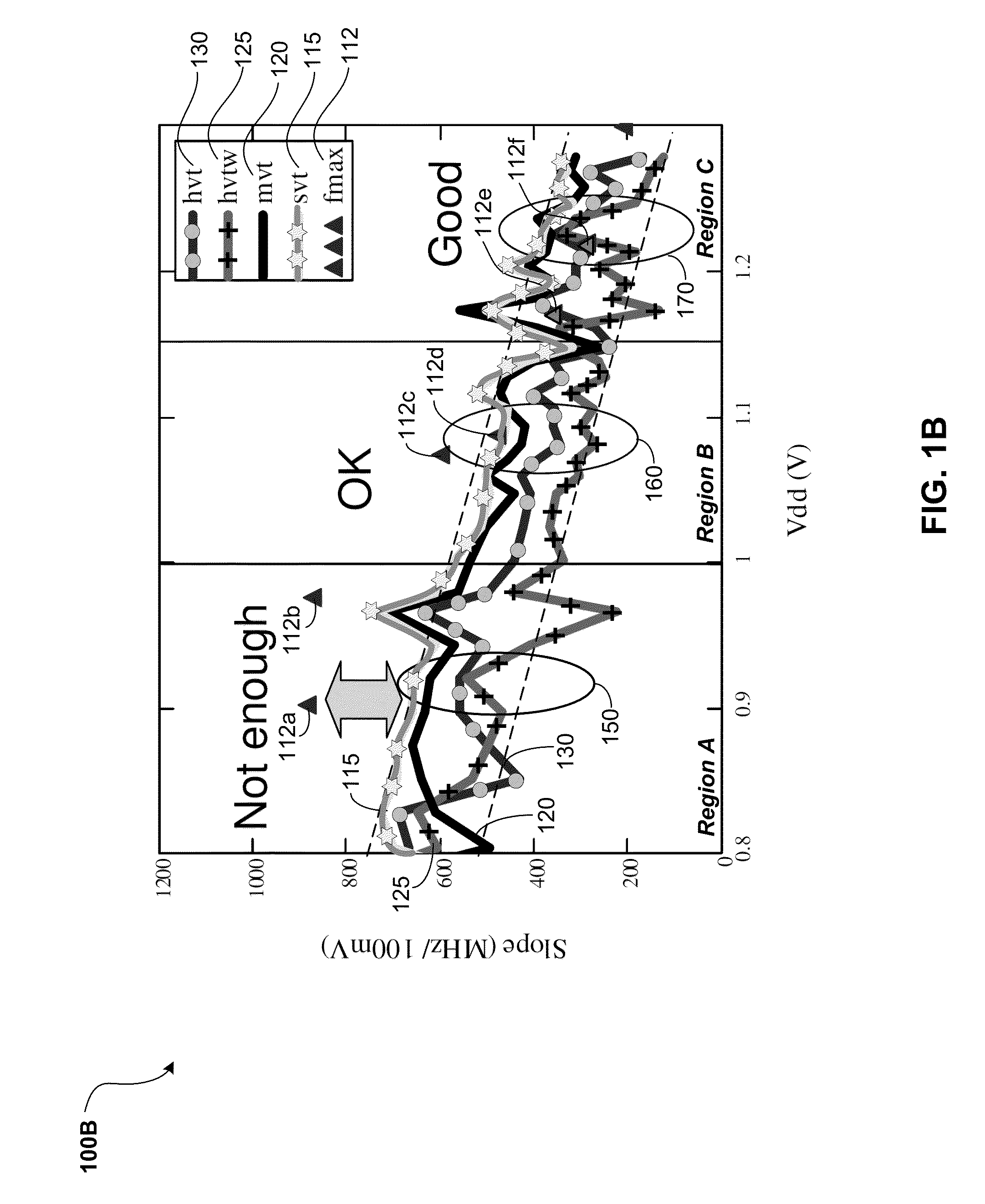
[0018]The following one or more exemplary embodiments describe emulation circuits that may be present within microprocessor devices. Particularly, the circuits emulate system critical paths across a range of microprocessor supply voltages (i.e., Vdd), whereby the system critical paths may be paths within the microprocessor design that limit frequency (i.e., the slowest path). The system critical paths may be emulated by one or more delay circuits that create different delay values in response to changes to microprocessor supply voltages (i.e., Vdd) undesirably caused by, for example, voltage droop. The changes in delay provide a means for sensing voltage droop and accordingly correcting the frequency value of the microprocessor's on-chip clock. This sensing and subsequent adjustment to the microprocessor's on-chip clock frequency maintains an adequate frequency guardband between the actual clock frequency and the maximum operating frequency (fmax) of the microprocessor. The followin...


PUM


Abstract

A circuit for monitoring and controlling a clock signal generated by a clock source in a microprocessor device may include a voltage divider network that provides a plurality of voltages, a selector device that receives the plurality of voltages and provides a scaled supply voltage and a scaled ground voltage from the plurality of voltages, and at least one delay element that receives the scaled supply voltage and the scaled ground voltage and generates a delayed pulse signal by applying a delay to each pulse of the clock signal. The delayed pulse signal may include a delay magnitude that is controllable by the scaled supply voltage and the scaled ground voltage, such that the delayed pulse signal is used to generate a frequency correction signal based on a variation to a supply voltage of the microprocessor. The frequency correction signal may then be applied to the clock source.

Description

BACKGROUND[0001]a. Field of the Invention[0002]The present invention generally relates to microprocessors, and more particularly to maintaining the performance of such microprocessors using control circuitry.[0003]b. Background of Invention[0004]Microprocessor devices should operate reliably across a variety of environmental conditions. One occurrence associated with microprocessor environments is voltage droop, whereby as a result of, for example, changes in current load, the supply voltage momentarily drops. Voltage droop may in turn affect the maximum operating frequency (fmax) of the microprocessor compared to the actual frequency at which the microprocessor is being driven. For example, the microprocessor may be operating at a nominal clock frequency of 4.5 GHz, while the maximum operating frequency (fmax) of the microprocessor may be characterized as being 4.7 GHz. Thus, a guardband of 200 MHz (i.e., 4.7 GHz−4.5 GHz=0.2 MHz) exists.[0005]According to one scenario, a voltage dr...

Claims


Application Information

Patent Timeline
IPC IPC(8): G06F1/26
CPCG06F1/26G06F1/324Y02D10/00G06F1/08
Inventor DRAKE, ALAN J.HUI, DAVID T.OWCZARCZYK, PAWELTINER, MARSHALL D.YUAN, XIAOBIN
Owner GLOBALFOUNDRIES INC
Why Eureka
Try Eureka