Semiconductor integrated circuit

a technology of integrated circuits and semiconductors, applied in the field of temperature detection, can solve the problems of increasing the mounting area of temperature sensors, increasing the number of measurement points, and increasing the cost of them

Inactive Publication Date: 2009-03-05
KK TOSHIBA
View PDF18 Cites 11 Cited by
  • Summary
  • Abstract
  • Description
  • Claims
  • Application Information

AI Technical Summary

Problems solved by technology

In the temperature sensor described in JP-A-10-260082, the temperature sensor can measure a temperature with high precision, the cost thereof increases, and that the mounting area of the temperature sensor is increased.
Additionally, because the temperature sensor is provided outside the semiconductor integrated circuit (LSI circuit), the number of measurement points cannot be increased.

Method used


Image

  • Semiconductor integrated circuit
  • Semiconductor integrated circuit
  • Semiconductor integrated circuit

Examples


embodiment 1

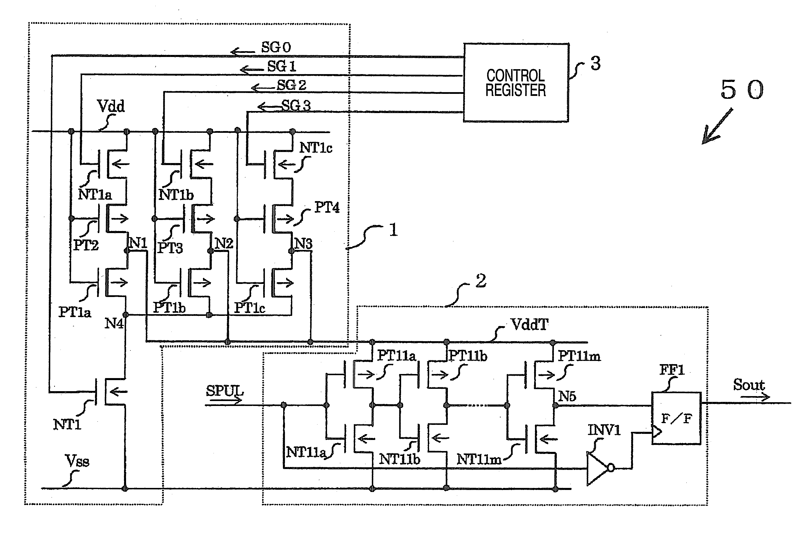
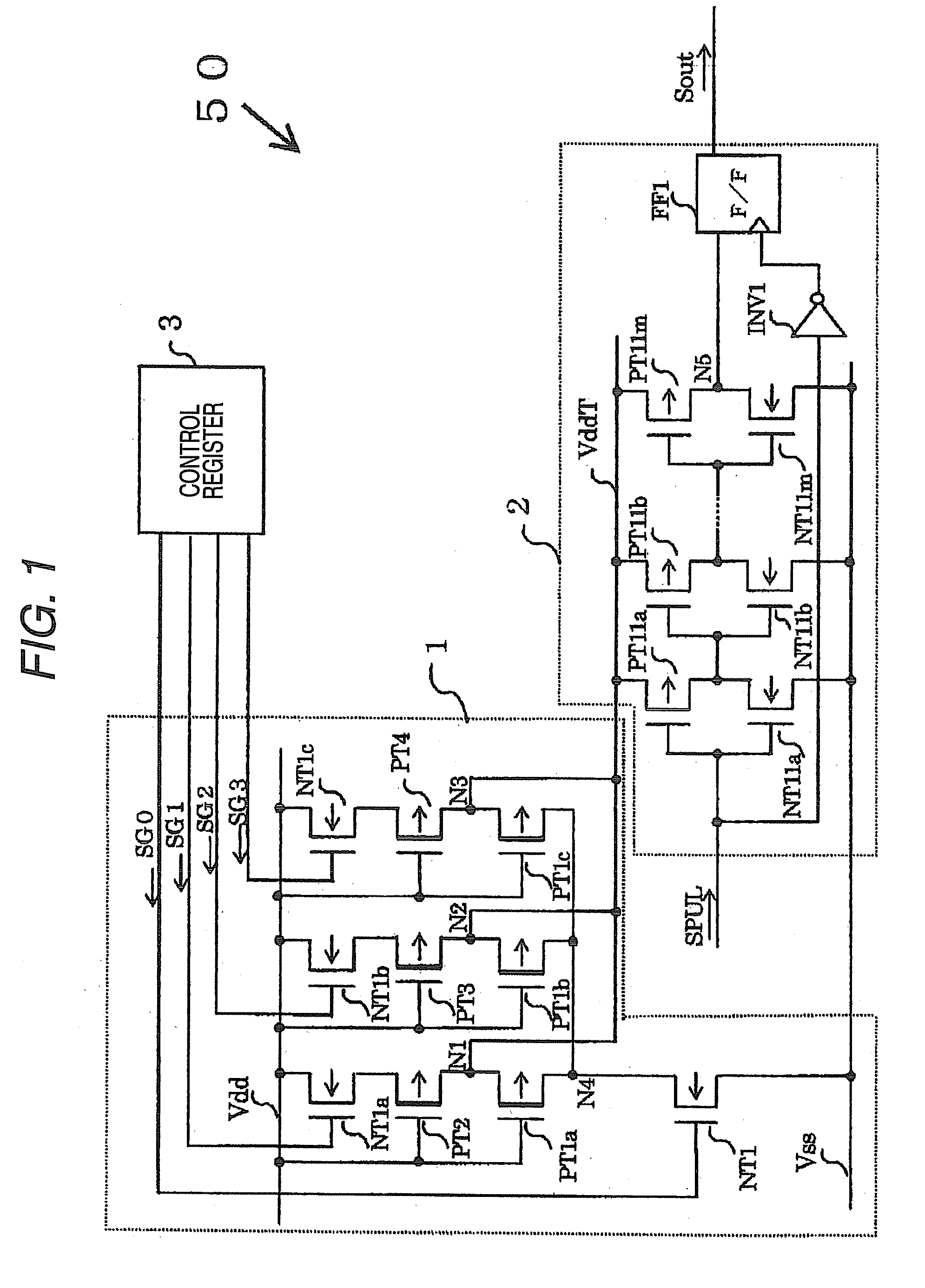
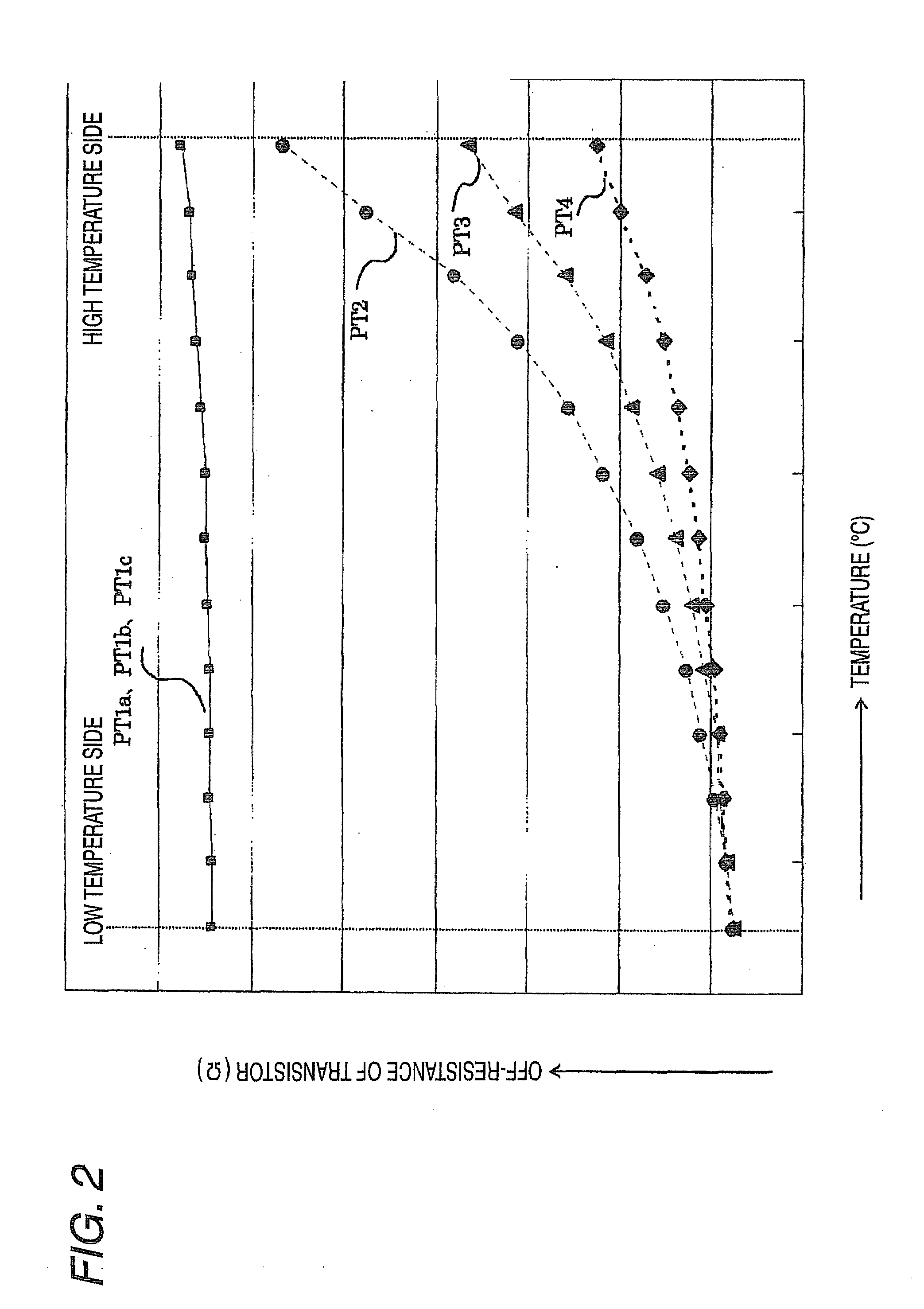
[0020]First, a temperature detection circuit according to Embodiment 1 of the invention is described with reference to the accompanying drawings. FIG. 1 is a circuit diagram illustrating the temperature detection circuit according to Embodiment 1 of the invention. FIG. 2 is a graph illustrating the temperature dependence of the off-resistance of a D-type P-channel metal oxide semiconductor (MOS) transistor constituting a voltage generating circuit portion according to Embodiment 1 of the invention. FIG. 3 is a diagram illustrating an operation of the voltage generating circuit portion according to Embodiment 1 of the invention. FIG. 4 is a graph illustrating the temperature dependence of a dropped high-potential-side power supply voltage output from the voltage generating circuit portion according to Embodiment 1 of the invention. In the present embodiment, a temperature is detected using a dropped high-potential power supply voltage having temperature dependence, and an inverter ch...

embodiment 2

[0057]Next, a temperature detection circuit according to Embodiment 2 of the invention is described below with reference to the accompanying drawings. FIG. 7 is a circuit diagram illustrating the voltage generating circuit portion according to Embodiment 2 of the invention. FIG. 8 is a diagram illustrating an operation of the voltage generating circuit portion according to Embodiment 2 of the invention The voltage generating circuit portion according to the present embodiment generates a dropped high-potential-side power supply voltage, which has temperature dependence, using the on-resistance of an N-channel MIS transistor.

[0058]Hereinafter, components of the present embodiment, which are the same as associated-components of Embodiment 1, are designated by the same reference numerals as reference numerals designating the associated-components used in Embodiment 1. Thus, the description of such components of Embodiment 2 is omitted. In the following description, only the differences...

embodiment 3

[0077]Next, a temperature detection circuit according to Embodiment 3 of the invention is described below with reference to the accompanying drawings. FIG. 9 is a circuit diagram illustrating a temperature detection circuit according to Embodiment 3 of the invention. FIG. 10 is a graph illustrating the temperature dependence of resistances constituting a voltage generating circuit portion according to Embodiment 3 of the invention. FIG. 11 is a graph illustrating a temperature detected by the temperature detection circuit according to Embodiment 3 of the invention. The voltage generating circuit portion according to the present embodiment generates a dropped high-potential-side power supply voltage, which has temperature dependence, using resistors.

[0078]Hereinafter, components of the present embodiment, which are the same as associated-components of Embodiment 1, are designated by the same reference numerals as reference numerals designating the associated-components used in Embodi...


PUM

PropertyMeasurementUnit
temperatureaaaaaaaaaa
voltageaaaaaaaaaa
temperature coefficientaaaaaaaaaa

Abstract

A temperature detection circuit includes: a voltage generator that is connected to a first voltage line having first voltage and a second voltage line having second voltage and to output a third voltage to a third voltage line, the third voltage being obtained by transforming the first voltage to be stepped down as an ambient temperature becomes higher; and a detecting unit that includes: a delay section that is connected to the second voltage line and the third voltage line and to receive a pulse signal, the delay section being configured to output a delayed pulse signal that is obtained by delaying the pulse signal for a delay time set to be longer as the third voltage becomes lower; and a temperature detecting section that is configured to: receive the delayed pulse signal and the pulse signal; latch the delayed pulse signal based on the pulse signal; output the latched signal as a detection result.

Description

CROSS-REFERENCE TO RELATED APPLICATIONS[0001]This application claims priority from Japanese Patent Application 2007-227001, filed Aug. 31, 2007, the entire contents of which are incorporated herein by reference.BACKGROUND OF THE INVENTION[0002]1. Technical Field[0003]The present invention relates to temperature detection.[0004]2. Description of the Related Art[0005]With the advance of micropatterning, increase in the operating speed, and high-integration of a semiconductor element, an amount of self-heating of a semiconductor integrated circuit (large scale integration (LSI) circuit) increases. Also, the chip temperature of a semiconductor integrated circuit (LSI circuit) rises. The rise of the chip temperature causes the need for controlling electrical characteristics, such as a reference clock frequency to be used for a circuit operation and impedance of an output driver, according to a change in the temperature. A temperature sensor or the like provided outside a semiconductor in...

Claims


Application Information

Patent Timeline
Patent Type & Authority Applications(United States)
IPC IPC(8): G01K7/16
CPCG01K7/346G01K7/01
Inventor SHODA, TOMOAKI
Owner KK TOSHIBA
Why Eureka
Try Eureka