High-resolution varactors, single-edge triggered digitally controlled oscillators, and all-digital phase-locked loops using the same

a technology of digital phase lock and high-resolution, applied in pulse generators, pulse manipulation, pulse techniques, etc., can solve problems such as poor noise immunity

Inactive Publication Date: 2008-05-15
IND TECH RES INST
View PDF25 Cites 12 Cited by
  • Summary
  • Abstract
  • Description
  • Claims
  • Application Information

AI Technical Summary

Benefits of technology

[0016]Consistent with embodiments of the present invention, there is also provided an ADPLL that includes a digitally controlled oscillator (DCO) for generating an oscillation signal, a frequency divider coupled to receive the oscillation signal and to generate a divided frequency signal, wherein a ratio of a frequency of the oscillation signal to a frequency of the divided frequency signal is a predetermined number; a control unit coupled to receive a reference signal having a reference frequency and the divided frequency signal; a coarse tuning part; and a fine tuning part. The DCO includes at least one delay circuit including at least one digitally controlled varactor (DCV), wherein the DCV includes a transistor having a gate, a source, a drain, and a substrate, wherein at least one of the gate, the source, the drain, and the substrate is coupled to receive one of two or more voltages, wherein at least one of the two or more voltages is not a power supply voltage or ground. The coarse tuning part includes a counter coupled to the control unit for counting cycles of the oscillation signal during one cycle of the reference signal, a comparator for comparing the counted number of cycles of the oscillation signal during one cycle of the reference signal with the predetermined number, a first successive approximation register (SAR) for generating a first control signal based on a result of the comparing of the counted number with the predetermined number, and a first up/down counter coupled to receive the first control signal for generating a first control word for adjusting the frequency of the oscillation signal. The fine tuning part includes a phase and frequency detector coupled to the control unit for comparing a phase of the divided frequency signal with a phase of the reference signal, a second SAR for generating a second control signal based on a result of the comparing of the phase of the divided frequency signal with that of the reference signal, and a second up/down counter coupled to receive the second control signal for generating a second control word for adjusting the frequency of the oscillation signal.
[0017]Consistent with embodiments of the present invention, there is further provided an all-digital phase-locked loop (ADPLL) that includes a digitally controlled oscillator (DCO) for generating an oscillation signal; a frequency divider coupled to receive the oscillation signal and to generate a divided frequency signal, wherein a ratio of a frequency of the oscillation signal to a frequency of the divided frequency signal is a predetermined n

Problems solved by technology

The VCO is an analog circuit, which occupies

Method used


Image

  • High-resolution varactors, single-edge triggered digitally controlled oscillators, and all-digital phase-locked loops using the same
  • High-resolution varactors, single-edge triggered digitally controlled oscillators, and all-digital phase-locked loops using the same
  • High-resolution varactors, single-edge triggered digitally controlled oscillators, and all-digital phase-locked loops using the same

Examples


first embodiment

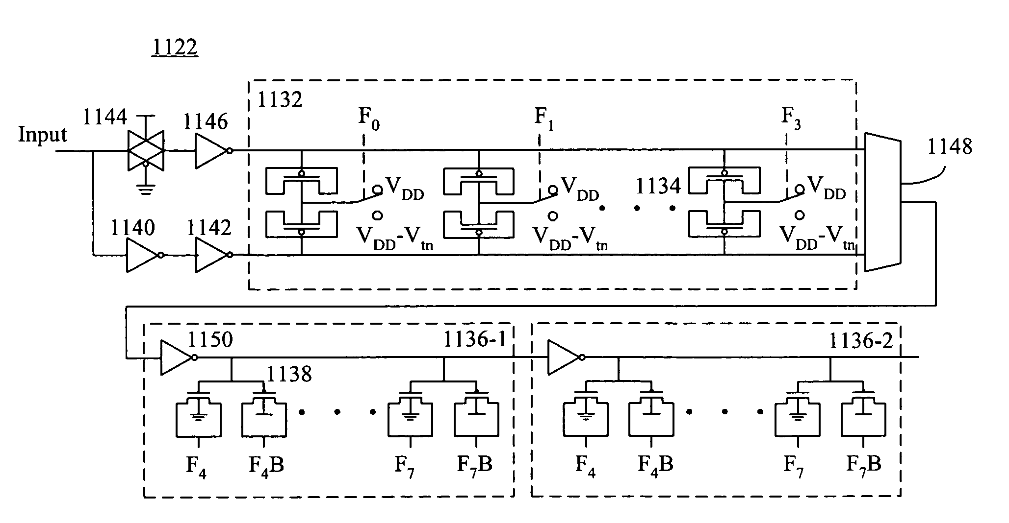
[0045]FIG. 7A shows a PMOS transistor 700 configured as a varactor consistent with the present invention. PMOS transistor 700 has a gate, a source, a drain, and a substrate. The substrate of PMOS transistor 700 is connected to a positive power supply VDD. The source and drain of PMOS transistor 700 are each coupled to receive one of four bias voltages, i.e., VDD, VDD-Vtn, Vtp, and GND, where Vtp is the threshold voltage of PMOS transistor 700, Vtn is the threshold voltage of an NMOS transistor having dimensions similar to those of PMOS transistor 700, and GND is ground.

[0046]By applying different combinations of bias voltages on the source and drain of PMOS transistor 700, PMOS transistor 700 may have different gate capacitances. FIG. 7B is a graph showing the change of the gate capacitance of PMOS transistor 700 with a gate voltage applied to the gate of PMOS transistor 700, under different source and drain bias conditions. The abscissa shows the gate voltage and the ordinate shows...

second embodiment

[0047]FIG. 8A shows a PMOS transistor 800 configured as a varactor consistent with the present invention. PMOS transistor 800 has a gate, a source, a drain, and a substrate. The source and drain of PMOS transistor 800 are both connected to the gate of PMOS transistor 800. The substrate of PMOS transistor 800 is coupled to receive one of two bias voltages, i.e., VDD and VDD-Vtn.

[0048]By varying the substrate bias voltage, PMOS transistor 800 may have different gate capacitances. FIG. 8B is a graph showing the change of the gate capacitance of PMOS transistor 800 with a voltage applied to the gate of PMOS transistor 800, Vc, under different substrate biases. The abscissa shows the gate voltage and the ordinate shows the gate capacitance. Roman numerals I and II represent different substrate voltages, as given in Table III below. Table III also shows simulation results of the gate capacitance of PMOS transistor 800 under different source and drain biases of PMOS transistor 800. The cur...

third embodiment

[0049]FIG. 9A shows a PMOS transistor 900 configured as a varactor consistent with the present invention. PMOS transistor 900 has a gate, a source, a drain, and a substrate. The source and drain of PMOS transistor 900 are connected to each other. The gate of PMOS transistor 900 is coupled to receive one of three bias voltages, i.e., VDD, |Vtp|, and GND. The substrate of PMOS transistor 900 is biased at VDD.

[0050]By varying the gate bias voltage, PMOS transistor 900 may have different source / drain (S / D) capacitances. FIG. 9B is a graph showing the change of the S / D capacitance of PMOS transistor 900 with a voltage applied to the source and drain of PMOS transistor 900, Vc, under different gate biases. The abscissa shows the S / D voltage and the ordinate shows the S / D capacitance. Roman numerals I, II, and III represent different gate voltages, as given in Table IV below. Table IV also shows simulation results of the gate capacitance of PMOS transistor 900 under different source and dr...


PUM


Abstract

A digitally controlled oscillator (DCO) includes a pulse generator for generating a pulse signal upon an edge of a trigger signal, and at least one delay circuit coupled to delay the pulse signal generated by the pulse generator. The pulse generator is coupled to receive one of the delayed pulse signal from the at least one delay circuit and an enable signal as the trigger signal. A digitally controlled varactor (DCV) includes a transistor having a gate, a source, a drain, and a substrate, wherein at least one of the gate, the source, the drain, and the substrate is coupled to receive one of two or more voltages, wherein at least one of the two or more voltages is not a power supply voltage or ground.

Description

FIELD OF THE INVENTION[0001]This invention relates in general to high-resolution varactors, single-edge triggered digitally controlled oscillators, and all-digital phase-locked loops using the same.BACKGROUND[0002]In high-speed integrated circuit (IC) processors or communications systems, phase-locked loops (PLL) are often used to obtain clock signals with accurate frequencies and phases. For example, in a radio frequency (RF) transmitter, a PLL may be used to synthesize a carrier frequency based on a reference frequency; and in an RF receiver, a PLL may be used to recover the carrier frequency from the received signals. For another example, in a system composed of multiple IC chips, PLL's may be used in the chips for synchronization with one another, or to provide internal clock signals having precise timing relationships but higher frequencies than external signals.[0003]Examples of conventional PLL's include linear PLL's, digital PLL's, and all-digital PLL's. These three types ar...

Claims


Application Information

Patent Timeline
IPC IPC(8): H03L7/08H01L29/94H03B28/00
CPCH03K3/0315H03K5/133H03K5/1534H03L2207/50H03K2005/00293H03L7/0991H03K2005/00071
Inventor HUANG, HONG-YILIU, JEN-CHIEHCHU, YUAN-HUA
Owner IND TECH RES INST
Why Eureka
Try Eureka