Airbag device

A technology of airbags and mounting plates, which is applied in the directions of transportation and packaging, steering control installed in vehicles, pedestrian/passenger safety layout, etc., and can solve problems such as increased weight and increased material costs

Inactive Publication Date: 2012-12-05
ASHIMORI INDS
View PDF6 Cites 8 Cited by
  • Summary
  • Abstract
  • Description
  • Claims
  • Application Information

AI Technical Summary

Problems solved by technology

Therefore, the rib surrounding the outer periphery of the holding member becomes a factor of increased material cost and increased weight.

Method used


Image

  • Airbag device
  • Airbag device
  • Airbag device

Examples


Embodiment Construction

[0041] Hereinafter, the structure of the mounting portion of the airbag device according to the embodiment will be described. figure 1 It is an exploded perspective view showing the steering wheel 10 and the airbag device 30 .

[0042] The attachment portion structure of the airbag device 30 is a structure for attaching the airbag device 30 to the steering wheel 10 .

[0043] The steering wheel 10 is a member for steering the vehicle, and has a wheel body 12 , spokes 14 , and a core member 16 as a central member. The disk body 12 is a part that receives the manipulation force exerted by a person. The spokes 14 are formed in a rod shape extending from the inner peripheral portion of the disc body 12 toward the center thereof, and are connected to the steering shaft at the center of the disc body 12 . Here, three spokes 14 are provided, but two or the like may be used.

[0044] The core member 16 is exposed at substantially the center of the steering wheel 10 . The core memb...


PUM


Abstract

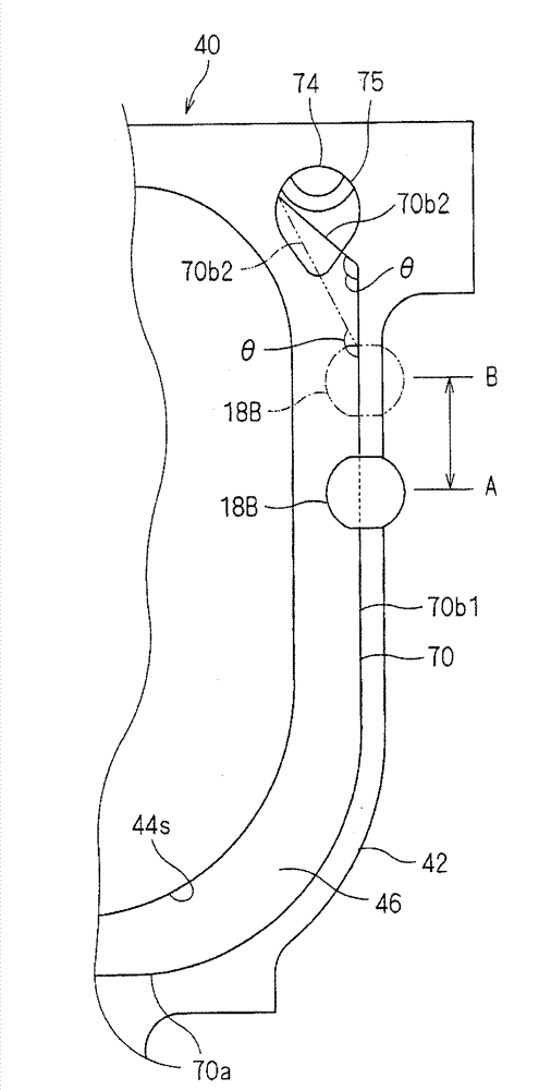
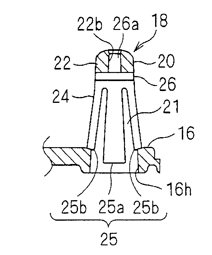
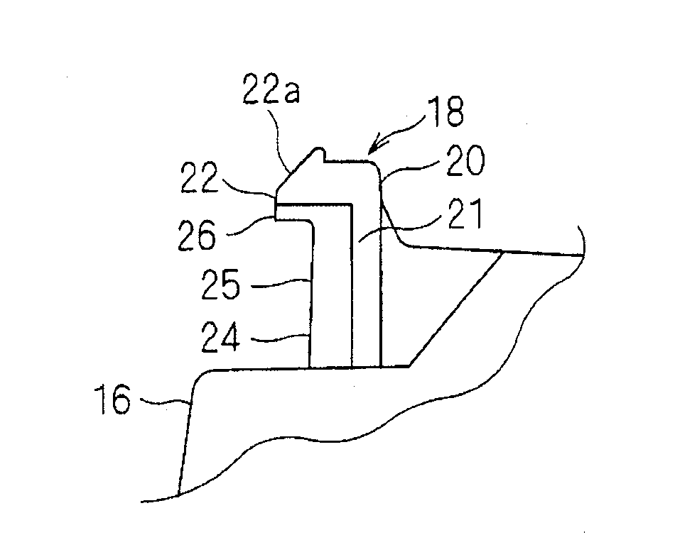
An airbag device is provided with: a mounting plate (40) to which an airbag, an inflator, and a cover are affixed; an engagement body (70) consisting of an elastically deformable linear material and formed in a shape having a pair of side wire portions (70b) and an intermediate wire portion (70a) which are interconnected in a U-shape; and a holding member (60) for holding the engagement body (70) relative to the mounting plate (40). The respective ends of the pair of side wire portions are formed as tilted portions (70b2) for pressing. A pair of pressing auxiliary members (74) which can respectively make contact with the pair of tilted portions for pressing is provided to the mounting plate (40). The engagement body (70) is held relative to the mounting plate (40) while the pair of tilted portions (70b) for pressing are respectively made to contact with the pair of pressing auxiliary members (74) to press the intermediate wire portion (70a) in the direction in which the intermediate wire portion (70a) is engaged with a first mounting member (18A).

Description

technical field [0001] The present invention relates to a technique for installing an airbag device on a steering wheel. Background technique [0002] Conventionally, there is a technique disclosed in Patent Document 1 as a technique for attaching an airbag device to a steering wheel. [0003] In Patent Document 1, ribs protrude from the outer periphery of the holding member, and the locking wire is attached and arranged at the locking position inside the rib of the holding member with the entire diameter reduced. Then, the three pins on the steering wheel side are locked with the locking wires, thereby attaching the airbag module to the steering wheel. [0004] Patent Document 1: Japanese Unexamined Patent Publication No. 2002-2433. [0005] The problem to be solved by the invention [0006] However, in the technique disclosed in Patent Document 1, ribs are protruded from substantially the entire outer periphery of the holding member in order to reduce the diameter of th...

Claims


Application Information

Patent Timeline
Patent Type & Authority Applications(China)
IPC IPC(8): B60R21/203B62D1/16
CPCB60R21/203B60R21/16B60R21/20
Inventor 山路直树吉井畅彦山內景太
Owner ASHIMORI INDS
Why Eureka
Try Eureka