Feeding device for automatic shaft-riveting of transmission chain

A feeding device and transmission chain technology, applied in the direction of metal chains, etc., can solve the problems of low processing precision, low processing efficiency, and increased costs of the chain, and achieve the effects of reducing labor expenditure, improving efficiency, and saving costs

Inactive Publication Date: 2012-12-12
SUZHOU DELLFLY ELECTRONICS
View PDF0 Cites 6 Cited by
  • Summary
  • Abstract
  • Description
  • Claims
  • Application Information

AI Technical Summary

Problems solved by technology

[0002] At present, after the chain piece of the transmission chain is formed in the chain piece forming mold, the chain shaft is inserted between the two chain pieces by hand, and finally the chain shaft and the two chain pieces are riveted by pressure riveting technology, because there are manual parts in the process. Participation leads to low processing accuracy and low processing efficiency of the chain, and wastes manpower and increases costs

Method used


Image

  • Feeding device for automatic shaft-riveting of transmission chain
  • Feeding device for automatic shaft-riveting of transmission chain
  • Feeding device for automatic shaft-riveting of transmission chain

Examples


Embodiment Construction

[0014] The present invention is described below in conjunction with accompanying drawing.

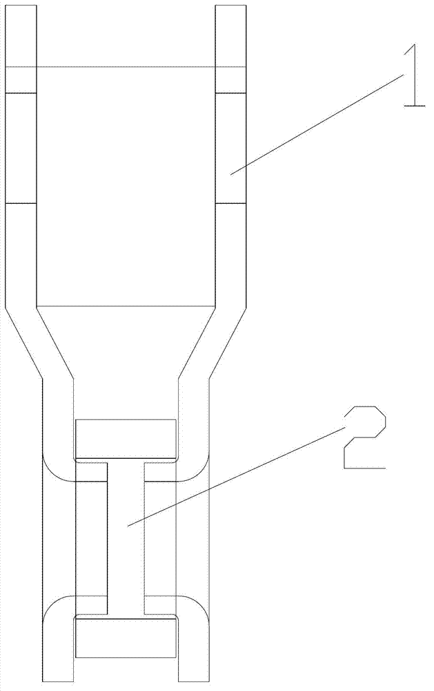
[0015] as attached figure 1 The shown schematic diagram of the chain structure of the present invention is mainly composed of a chain piece 1 and a chain shaft 2, and the chain piece is riveted together by turning over the chain shaft.

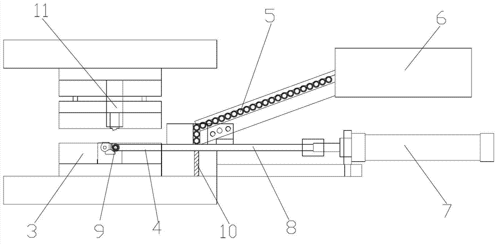
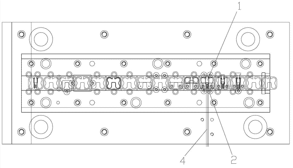
[0016] attached figure 2 , 3 It is a transmission chain automatic riveting shaft feeding device according to the present invention, which includes a chain forming die 3, on which the product material to be processed is placed, and the product material is processed step by step, and the product material is turned 90° A chain shaft introduction groove 4 is provided at the folding place; a material guide groove 5 is arranged obliquely above the 4 ends of the chain shaft introduction groove, and the discharge port of the material guide groove 5 is located directly above the chain shaft introduction groove 4, and the material guide groove The feeding end...


PUM


Abstract

The invention discloses a feeding device for the automatic shaft-riveting of a transmission chain, which comprises a chain forming die, and a chain shaft introducing groove is arranged on the chain forming die; a feed channel is aslant arranged above the chain shaft introducing groove; a discharge port of the feed channel is just over the chain shaft introducing groove; a feed end of the feed channel is connected with a vibration feed tray; and a junction between the discharge port and the chain shaft introducing groove is provided with a pushing mechanism, the pushing mechanism mainly consists of an air cylinder and a feeding push rod. According to the structural design of the feeding device, the feeding device pushes a chain shaft to the riveting position of a chain sheet and the chain shaft by using the cylinder expansion principle, wherein the chain shaft is conveyed into the chain shaft introducing groove through the vibration feed tray and the feed channel, the feeding device is high in automation degree, greatly increases the shaft-riveting efficiency of the chain, reduces the human and economy costs, saves the cost and improves the riveting precision of the chain.

Description

technical field [0001] The invention relates to a feeding device, in particular to a roller feeding device used for automatic riveting rollers of transmission chains. Background technique [0002] At present, after the chain piece of the transmission chain is formed in the chain piece forming mold, the chain shaft is inserted between the two chain pieces by hand, and finally the chain shaft and the two chain pieces are riveted by pressure riveting technology, because there are manual parts in the process. Participation leads to low processing accuracy and low processing efficiency of the chain, and wastes manpower and increases costs. Contents of the invention [0003] In view of the above-mentioned existing technical problems, the object of the present invention is to propose a transmission chain automatic riveting shaft feeding device for continuously and automatically conveying chain shafts. [0004] The technical solution of the present invention is realized in the fo...

Claims


Application Information

Patent Timeline
Patent Type & Authority Applications(China)
IPC IPC(8): B21L9/06
Inventor 邱惠新
Owner SUZHOU DELLFLY ELECTRONICS
Why Eureka
Try Eureka