Automatic riveting method and automatic riveting device

A technology of riveting and equipment, applied in the field of mechanical processing, can solve the problems of manual clamping difficulties, low production efficiency, low production efficiency, etc., and achieve the effect of ensuring the accuracy of riveting, maintaining the correct direction, and improving production efficiency

Pending Publication Date: 2019-08-20
深圳市正和首信精密科技有限公司
View PDF0 Cites 2 Cited by
  • Summary
  • Abstract
  • Description
  • Claims
  • Application Information

AI Technical Summary

Problems solved by technology

In the riveting process, the production efficiency is low and the labor cost is high by manually clamping workpieces and rivets
Especially for small rivets, manual clamping is more difficult, the production efficiency is very low, and a large amount of manpower is required, resulting in high labor costs, resulting in high production costs and limited competitiveness of enterprises

Method used


Image

  • Automatic riveting method and automatic riveting device
  • Automatic riveting method and automatic riveting device
  • Automatic riveting method and automatic riveting device

Examples


Embodiment 1

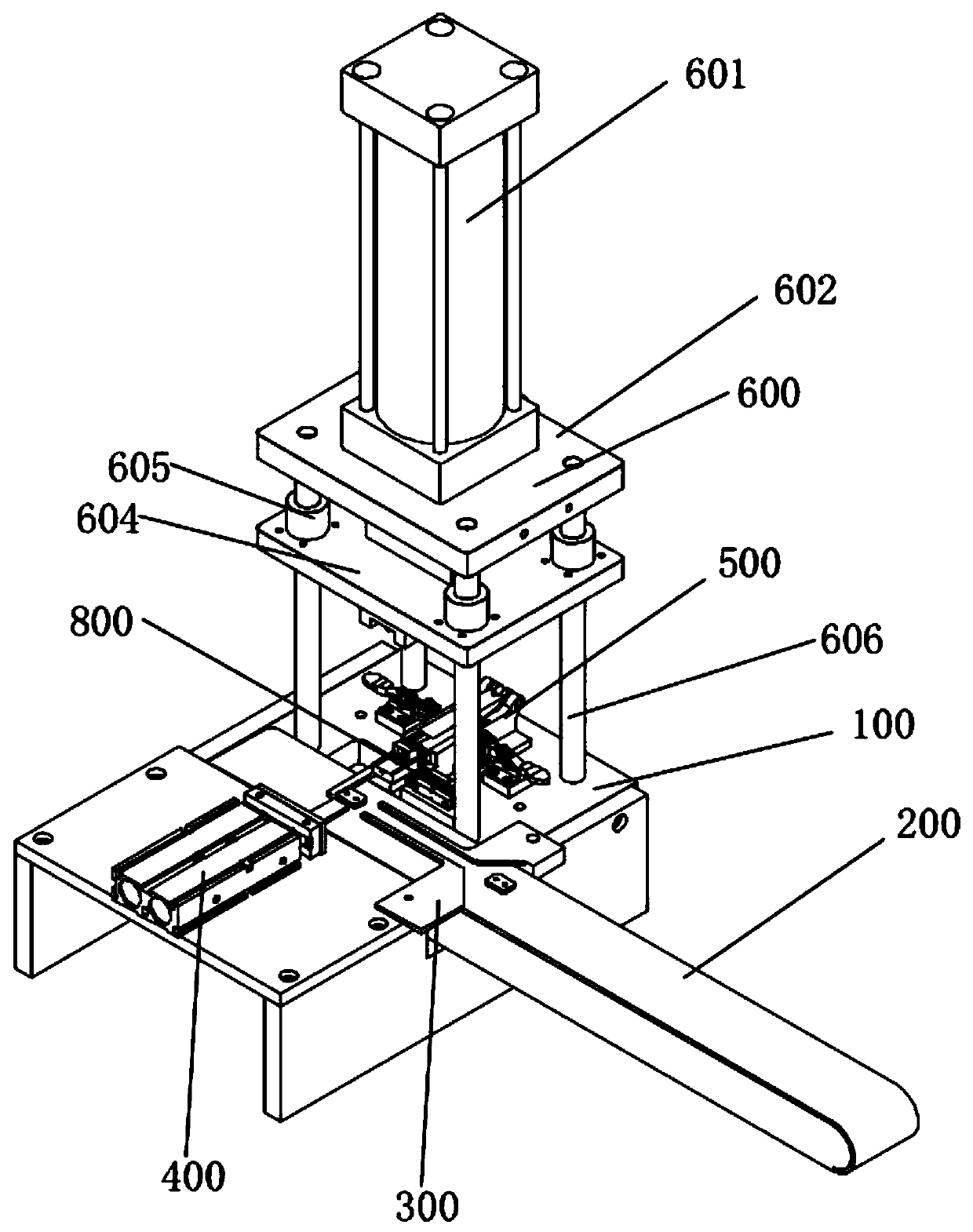
[0050] refer to figure 1 and Figure 7 , the automatic riveting equipment includes a bracket and a transmission mechanism 200, a direction correction mechanism 300, a workpiece clamping mechanism 400, a rivet clamping mechanism 500, a riveting mechanism 600, a positioning mechanism 700 and a blanking mechanism respectively arranged on the bracket 100. Collection agency 800.

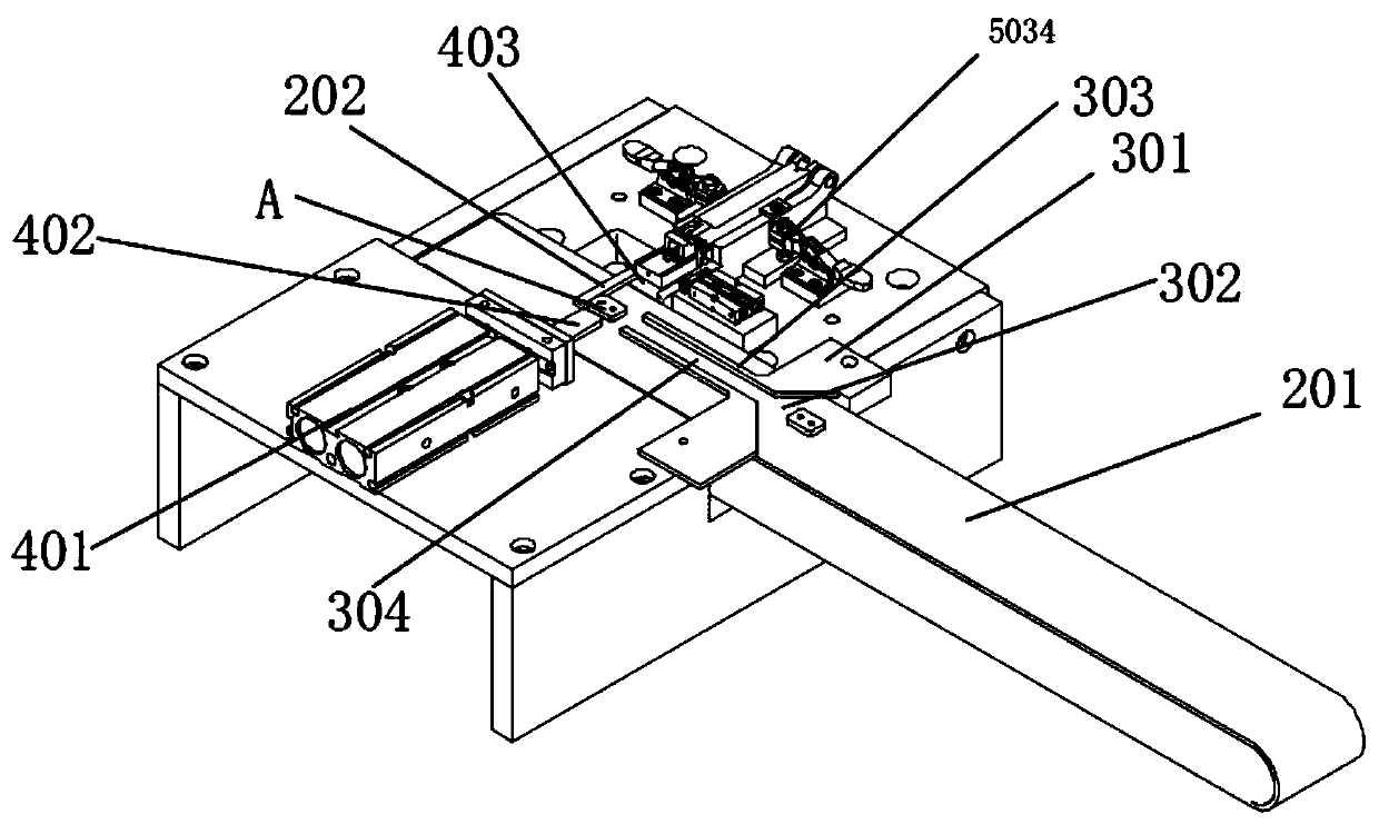
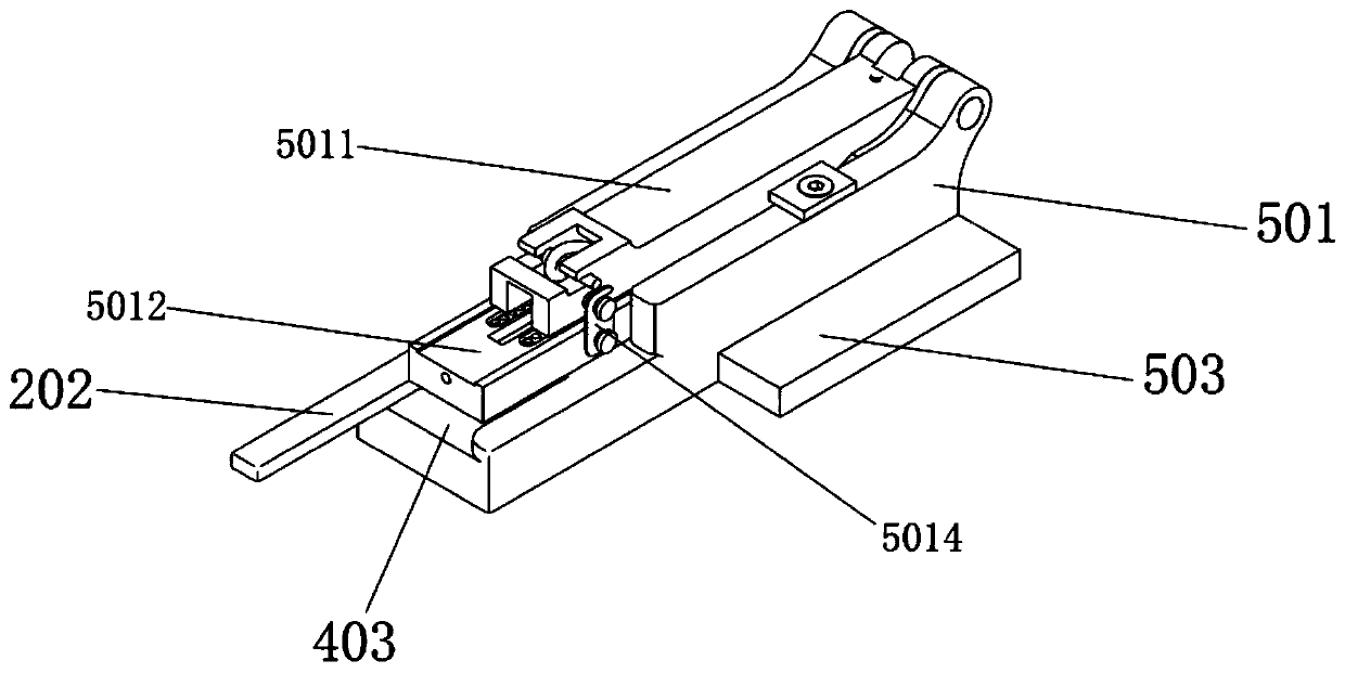
[0051] refer to figure 2 , the transmission mechanism includes a conveyor belt 201 for transporting the workpiece A and a material stop block 202 for stopping the workpiece, and the material stop block is arranged at the rear end of the conveyor belt and fixed above the conveyor belt.

[0052] refer to figure 2 , the direction correction mechanism includes a funnel-shaped correction groove 302 composed of two inclined blocks 301 with a wide front and a narrow rear, and an equal-width guide groove 304 with a width slightly larger than the width of the workpiece formed by two convex strips 303 arranged...

Embodiment 2

[0062] An automatic riveting method based on the above-mentioned automatic riveting equipment, comprising the following steps:

[0063] Step 1. Fix the rivet box loaded with rivets on the bracket. Specifically, the rivet box loaded with rivets is fixed on the interchangeable body, and then the interchangeable body is fixed on the bracket through quick clips.

[0064] Step 2, the conveyor belt transfers the workpiece.

[0065] Step 3. When the workpiece passes through the calibration groove, the calibration groove corrects the direction of the workpiece. The corrected workpiece is also guided to the stop block through the guide groove.

[0066] Step 4. The material stop block intercepts and stops the workpiece on the conveyor belt that has undergone direction correction and direction maintenance.

[0067] Step 5, the first driving cylinder drives the feeding block to push the stopped workpiece into the acupuncture point.

[0068] Step 6. The second driving cylinder drives t...


PUM


Abstract

The invention discloses an automatic riveting method and an automatic riveting device. The automatic riveting device comprises a support and further comprises a conveying mechanism, a direction correcting mechanism, a workpiece clamping mechanism, a rivet clamping mechanism and a riveting mechanism which are arranged on the support. The conveying mechanism comprises a conveyer belt used for conveying workpieces and a material stopping block used for stopping the workpieces. The direction correcting mechanism comprises a funnel-shaped correction groove with a wide front part and a narrow back part, and the correction groove is composed of inclined blocks. The workpiece clamping mechanism comprises a first drive cylinder, a feeding block and a groove station. The first drive cylinder is connected with the feeding block and drives the feeding block. The feeding block pushes the workpiece blocked and stopped by the material stopping block into the groove station. The rivet clamping mechanism comprises a rivet box and rivets arranged in the rivet box. The riveting mechanism comprises a second drive cylinder and a pressing block, wherein the second drive air cylinder drives the pressingblock to press the rivets in the rivet box into the workpieces in the groove station. The automatic riveting device achieves full-automatic riveting of the workpieces, greatly lowers labor investment,is low in labor cost and greatly improves production efficiency.

Description

technical field [0001] The invention relates to the technical field of mechanical processing, in particular to an automatic riveting method and automatic riveting equipment. Background technique [0002] At present, the riveted workpieces in the industry usually manually put the workpieces to be riveted into the jig, then manually put the rivets into the jig, and then start the riveting machine to press down. In the riveting process, the production efficiency is low and the labor cost is high by manually clamping workpieces and rivets. Especially in the case of small rivets, manual clamping is more difficult, the production efficiency is very low, and a large amount of manpower is required, resulting in high labor costs, resulting in high production costs and limited competitiveness of enterprises. Contents of the invention [0003] The main purpose of the present invention is to provide an automatic riveting equipment with high production efficiency and low cost. [000...

Claims


Application Information

Patent Timeline
Patent Type & Authority Applications(China)
IPC IPC(8): B21J15/10B21J15/20B21J15/38B21J15/32
CPCB21J15/10B21J15/20B21J15/32B21J15/38
Inventor 华秀菊朱华伟方圳彬赖文鑫凡夏杰梁贵华张冬平熊琦飞张俊唐卫宜
Owner 深圳市正和首信精密科技有限公司
Why Eureka
Try Eureka