Mushroom fastener riveting machine
What is Al technical title?
Al technical title is built by PatSnap Al team. It summarizes the technical point description of the patent document.
A riveting machine and mushroom button technology, which is applied to fasteners, buttons, clothing, etc., can solve the problems of low qualified rate of finished products and low processing efficiency of mushroom buttons, and achieve the effect of reducing the qualified rate and improving production efficiency
Inactive Publication Date: 2014-07-02
SHENZHEN LIANDA BUTTON
View PDF11 Cites 0 Cited by
Summary
Abstract
Description
Claims
Application Information
AI Technical Summary
This helps you quickly interpret patents by identifying the three key elements:
Problems solved by technology
Method used
Benefits of technology
Problems solved by technology
[0003] Aiming at the disadvantages of low processing efficiency and low qualified rate of finished products in the above-mentioned mushroom buckle in the prior art, the present invention provides a new mushroom buckle riveting machine, which can realize the automatic riveting of the upper and lower parts of the mushroom buckle, Not only can improve production efficiency, but also can improve the qualified rate of products
Method used
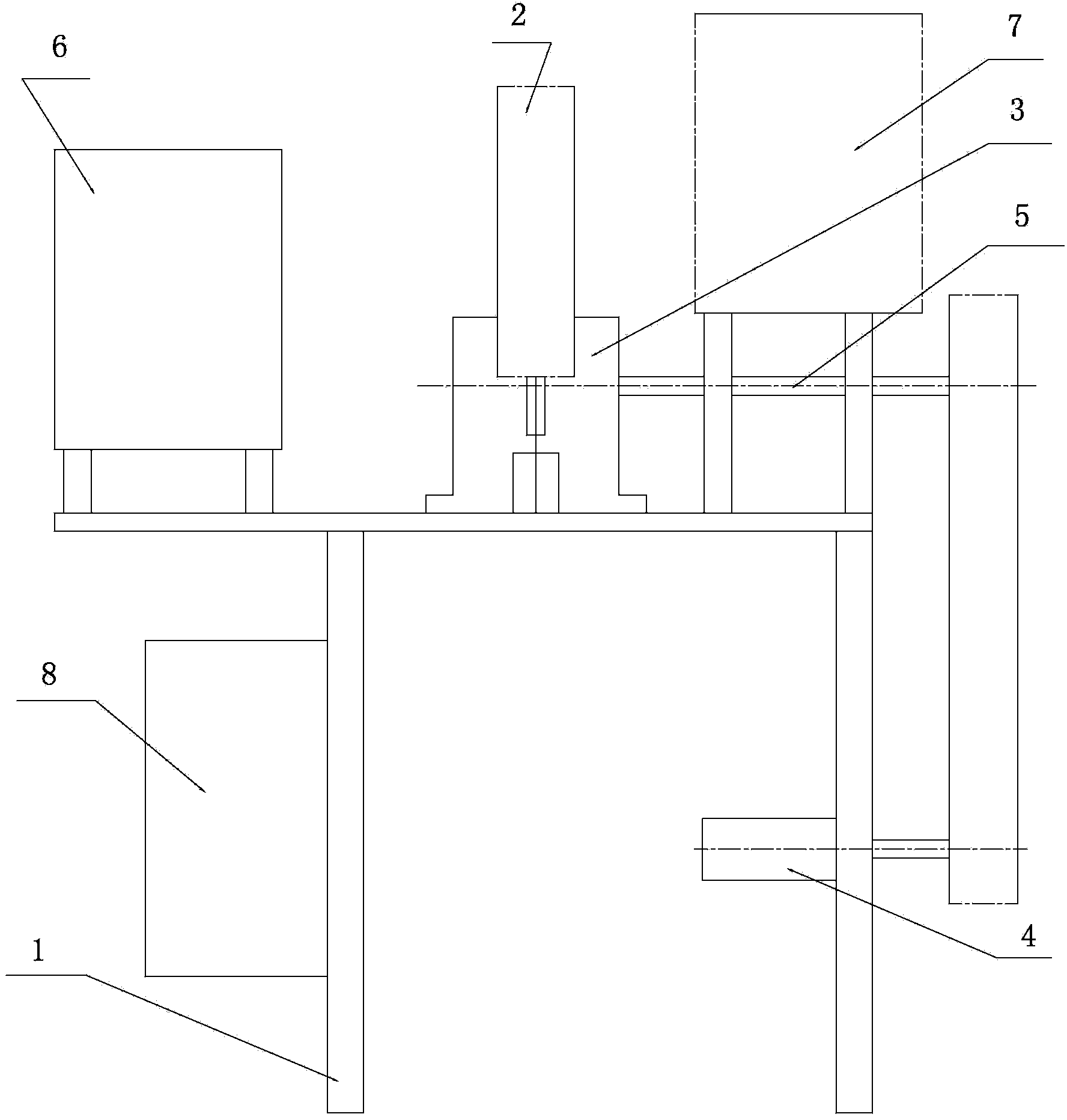
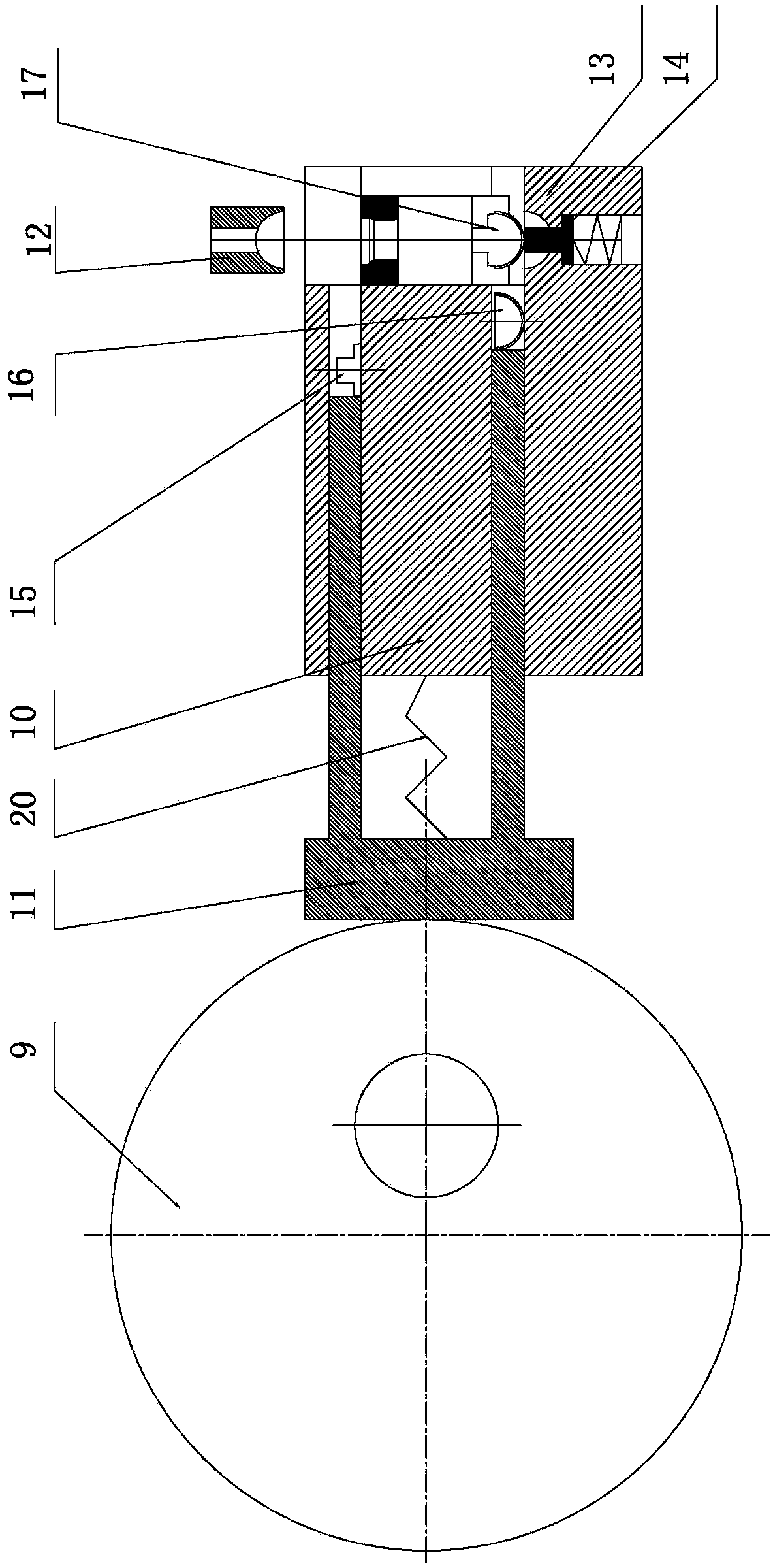
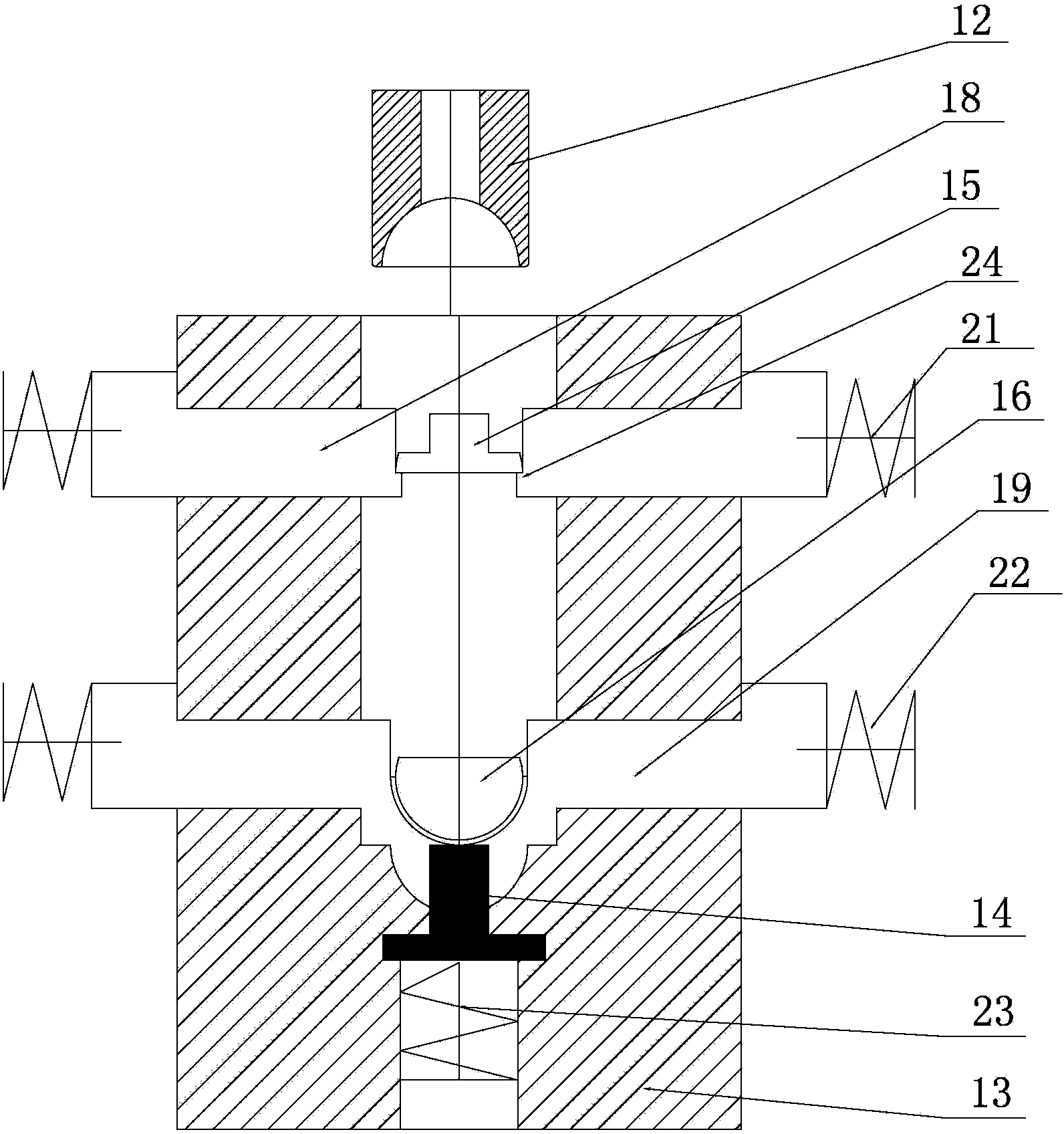
Image
Click on the blue label to locate the original text in one second.
Reading with bidirectional positioning of images and text.
Examples
Embodiment Construction
[0022] This embodiment is a preferred implementation mode of the present invention, and other principles and basic structures that are the same or similar to this embodiment are within the protection scope of the present invention.
[0023] Please see attached figure 1 , attached figure 2 And attached image 3 , the present invention includes a frame 1, a first vibrating plate 6, a second vibrating plate 7, a transmission system 2, a motor 4, a main shaft 5 and a riveting mechanism. In this embodiment, the top of the frame 1 is an operating platform, and the transmission system 2 Installed on the console, in the present embodiment, the transmission system seat 3 is installed on the console, and the transmission system 2 is installed on the transmission system seat 3. In this embodiment, the first vibrating plate 6 and the second vibrating plate 7 are fixedly installed on the frame 1, and the upper rivet 15 and the lower rivet of the mushroom buckle are respectively placed i...
PUM
Abstract
The invention discloses a mushroom fastener riveting machine. The riveting machine includes a rack, a first vibration disk, a second vibration disk, a transmission system, a motor, a main shaft and a riveting mechanism, the transmission system is arranged on the rack, the motor drives the main shaft to rotate, the main shaft outputs power to the transmission system, the transmission system drives the riveting mechanism to move, the riveting mechanism includes a support base, two slideways that are parallel from top to bottom are arranged inside the support base, two ejector rods are arranged on a top base, the two ejector rods are respectively arranged inside the two slideways, an upper riveting piece support is arranged at the exit of the upper slideway, a lower riveting piece support is arranged at the exit of the lower slideway, an upper mould is arranged above the upper riveting piece support, a lower mould is arranged below the lower riveting piece support, the upper mould and the lower mould are arranged below the riveting mechanism. In the invention, the automatic riveting of mushroom fasteners can be achieved, the production efficiency of mushroom fasteners can be greatly improved, during the riveting process, the fitting between the upper part and the lower part of mushroom fasteners can effectively guarantee the relative position of the two parts, so that the qualified rate of products is greatly increased.
Description
technical field [0001] The invention discloses a button processing machine, in particular to a mushroom button riveting machine. Background technique [0002] With the increasing diversification of button varieties, all kinds of buttons have already appeared in people's eyes. Now, there is a kind of button called "mushroom button", which is made of metal material, because its buckle surface is semicircular and looks like a mushroom, so it gets its name. The general mushroom buckle includes upper and lower parts, and the upper and lower parts are riveted together during production. Because the top surface of the upper and lower parts of the mushroom buckle is arc-shaped, it is difficult to place it on a plane for automatic processing. The current mushroom buckle is riveted manually, which not only has low production efficiency, but also, In the process of riveting, it is easy to produce defective products because the upper and lower parts of the mushroom buckle are ...
Claims
Application Information
Patent Timeline
Application Date:The date an application was filed.
Publication Date:The date a patent or application was officially published.
First Publication Date:The earliest publication date of a patent with the same application number.
Issue Date:Publication date of the patent grant document.
PCT Entry Date:The Entry date of PCT National Phase.
Estimated Expiry Date:The statutory expiry date of a patent right according to the Patent Law, and it is the longest term of protection that the patent right can achieve without the termination of the patent right due to other reasons(Term extension factor has been taken into account ).
Invalid Date:Actual expiry date is based on effective date or publication date of legal transaction data of invalid patent.