Mechanical-side drive fork-type roader roller

A technology for driving forks and road rollers, which is applied in the field of road rollers, can solve the problems of poor welt performance of rolling wheels, increased construction cost, poor compaction performance, etc., and achieves the effects of good welt performance, improved work efficiency, and large driving torque.

Inactive Publication Date: 2012-12-12
洛阳信全源机械设备有限公司
View PDF6 Cites 2 Cited by
  • Summary
  • Abstract
  • Description
  • Claims
  • Application Information

AI Technical Summary

Problems solved by technology

The side drive of the road roller with mechanical main drive of this structure mostly adopts chain direct transmission or gear direct transmission. Due to this limitation, the width of the road roller frame is mostly larger than the width of the rolling wheel, resulting in poor weltability of the rolling wheel , there are about 0.1-0.3 meters of the roadside end that cannot be compacted, and it is necessary to configure small compaction equipment to supplement the pressure on the side of the curb.
Cause a lot of waste of manpower and material resources
Due to the limitation of the transmission mode, the compaction performance is poor, which affects the construction quality
When maintaining the road surface, it is necessary to remove the curbs on the side of the road, which brings a lot of inconvenience to the construction and increases the construction cost
Although the width of the rollers of the existing hydraulically driven pronged road rollers can be greater than the width of the frame to achieve edge compaction, the manufacturing cost of the hydraulically driven equipment is high, the product price is expensive, and the operating technology requirements are high. , and difficult to maintain

Method used


Image

  • Mechanical-side drive fork-type roader roller
  • Mechanical-side drive fork-type roader roller

Examples


Embodiment Construction

[0012] In conjunction with the accompanying drawings, the following embodiments of the present invention are given, but the present invention is not limited to the following embodiments.

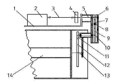
[0013] Such as figure 2 Shown: The machine-side drive fork-leg road roller described in this embodiment is mainly composed of a body 1 , a drive wheel 14 , a vibrating wheel 15 , an articulating frame 17 , fork legs 18 and a transmission mechanism 16 . The transmission mechanism is a mechanical side transmission structure, which is located on the side of the fuselage and the driving wheel.

[0014] Such as figure 1 Shown: the power of the driving system - the diesel engine is transmitted to the driving wheel 14 through the gearbox 2, universal joint drive shaft 3, brake hub 4 and transmission mechanism 16 installed on the body 1, so that the road roller can be compacted and driving. The transmission mechanism 16 is located on the side of the fuselage 1 and the driving wheel 14 , and ...


PUM


Abstract

The invention discloses a mechanical-side drive fork-type road roller which comprises a body (1), a drive wheel (14), a vibrating wheel (15), a hinge connector (17), forks (18) and a drive mechanism (16). The mechanical-side drive fork-type road roller is characterized in that the drive mechanism (16) is in a mechanical-side drive structure located on the side of the body (1) and the drive wheel (14). The problems that the existing road roller is unable to reach road sides, is poor in road side compacting performance, road-side reverse teeth need to be detached for repair or other compacting machines need to be added for supplementing compaction, and the like are well solved. The mechanical-side drive fork-type road roller has the advantages that side fitting performance is fine, road side fitting is achieved while compacting is effective, waste in manpower and resource materials is avoided, and operating efficiency is improved. The mechanical-side drive fork-type road roller is applicable to all serial mechanical drive fork-type road rollers.

Description

technical field [0001] The invention belongs to the technical field of road rollers, and mainly relates to a fork leg type road roller with mechanical side transmission. Suitable for all tandem mechanically driven prong rollers. Background technique [0002] At present, all kinds of known large, medium and small fork-leg road rollers have an overall structure in series. The side drive of the road roller with mechanical main drive of this structure mostly adopts chain direct transmission or gear direct transmission. Due to this limitation, the width of the road roller frame is mostly larger than the width of the rolling wheel, resulting in poor weltability of the rolling wheel , There are about 0.1-0.3 meters of the roadside end that cannot be compacted, and it is necessary to configure small compaction equipment to supplement the pressure on the side of the curb. Cause very big waste of manpower and material resources. Due to the limitation of the transmission mode, the ...

Claims


Application Information

Patent Timeline
Patent Type & Authority Applications(China)
IPC IPC(8): E01C19/26
Inventor 卢锡忠崔红尚张文策韩晓辉
Owner 洛阳信全源机械设备有限公司
Why Eureka
Try Eureka