Suppression method of relative intensity noise of light source of fiber-optic gyroscope

A relative intensity noise, fiber optic gyroscope technology, applied in Sagnac effect gyroscopes and other directions, can solve the problem of the relative intensity noise limitation of the light source of the static performance of the fiber optic gyroscope, and achieve the effect of improving the static performance

Inactive Publication Date: 2014-12-10
ZHEJIANG UNIV
View PDF6 Cites 0 Cited by
  • Summary
  • Abstract
  • Description
  • Claims
  • Application Information

AI Technical Summary

Problems solved by technology

[0009] Aiming at the problem that the static performance of the current fiber optic gyroscope, especially the high-precision fiber optic gyroscope system, is limited by the relative intensity noise of the light source, the purpose of the present invention is to provide a method for suppressing the relative intensity noise of the light source, which can effectively suppress the relative intensity noise of the light source, thereby improving Static Performance of Fiber Optic Gyroscope

Method used


Image

  • Suppression method of relative intensity noise of light source of fiber-optic gyroscope
  • Suppression method of relative intensity noise of light source of fiber-optic gyroscope
  • Suppression method of relative intensity noise of light source of fiber-optic gyroscope

Examples


Embodiment Construction

[0026] The present invention will be further described below in conjunction with accompanying drawing.

[0027] Invention principle:

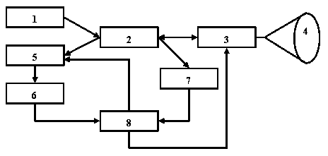
[0028] Such as figure 2 As shown, an optical intensity modulator 5 is added between the coupler 2 and the photodetector 6, and the optical fiber gyroscope signal light is modulated by the optical intensity modulator 5 to compensate the signal fluctuation caused by the relative intensity noise of the light source; the optical intensity modulation The control signal is derived from the reference light by the dead end of the optical fiber of the coupler 2 and obtained through a series of signal processing.

[0029] The light source power I(t) can be expressed as a DC component I 0 (t) and the noise component I n The sum of (t), namely:

[0030] I(t)=I 0 (t)+I n (t) (3)

[0031] The reference light with light intensity fluctuation information of the light source is drawn from the dead end of the optical fiber of the coupler 2, and the refer...


PUM


Abstract

The invention discloses a suppression method of relative intensity noise of a light source of a fiber-optic gyroscope. The suppression method comprises the following steps that: reference light which is lead out from an optical fiber dead head of a fiber-optic gyroscope coupler and has light source light-intensity variation information is received by a photoelectric detector to obtain a reference signal; the reference signal is processed by a signal processing module to generate a light intensity modulation control signal; light intensity modulation is performed on a fiber-optic gyroscope signal returned from a fiber-optic ring through a light intensity modulator; light intensity variation caused by the relative intensity noise of the light source is compensated; fiber-optic gyroscope signal light modulated by the light intensity is detected through another photoelectric detector; and the fiber-optic gyroscope signal light is modulated through the signal processing module to obtain the output of the fiber-optic gyroscope of which the relative intensity noise of the light source is suppressed. With the adoption of the suppression method of the relative intensity noise of the light source of the fiber-optic gyroscope, influence of the relative intensity noise of the light source, on the output of the fiber-optic gyroscope, can be effectively suppressed, and the static property of the fiber-optic gyroscope is improved.

Description

technical field [0001] The invention relates to a signal processing method in an optical fiber gyroscope sensor, in particular to a method for suppressing relative intensity noise of an optical fiber gyroscope light source. Background technique [0002] The white noise in the fiber optic gyroscope system is the main factor affecting the static performance of the fiber optic gyroscope, which can be characterized by the random walk coefficient. There are three basic sources of white noise in fiber optic gyroscopes: electronic additive noise, shot noise, and source relative intensity noise. Electronic additive noise mainly comes from the dark current of the detector and the Johnson thermal noise of the feedback resistor of the detector transimpedance amplifier, and its noise power has nothing to do with the power of the light source; the shot noise comes from the randomness of photoelectron emission during the detection process of the photodetector. It is caused by the quantum...

Claims


Application Information

Patent Timeline
Patent Type & Authority Patents(China)
IPC IPC(8): G01C19/72
Inventor 汪樟海陈杏藩刘承
Owner ZHEJIANG UNIV
Why Eureka
Try Eureka