

Driving assist device
An auxiliary device, driving state technology, applied in the control device, transportation and packaging, input parameters of external conditions, etc., can solve the problems of the reliability of the prediction result of the driving lane, and the inability to detect the distance stably.
- Summary
- Abstract
- Description
- Claims
- Application Information
AI Technical Summary
Problems solved by technology
Method used
Image

Examples
Embodiment approach 1
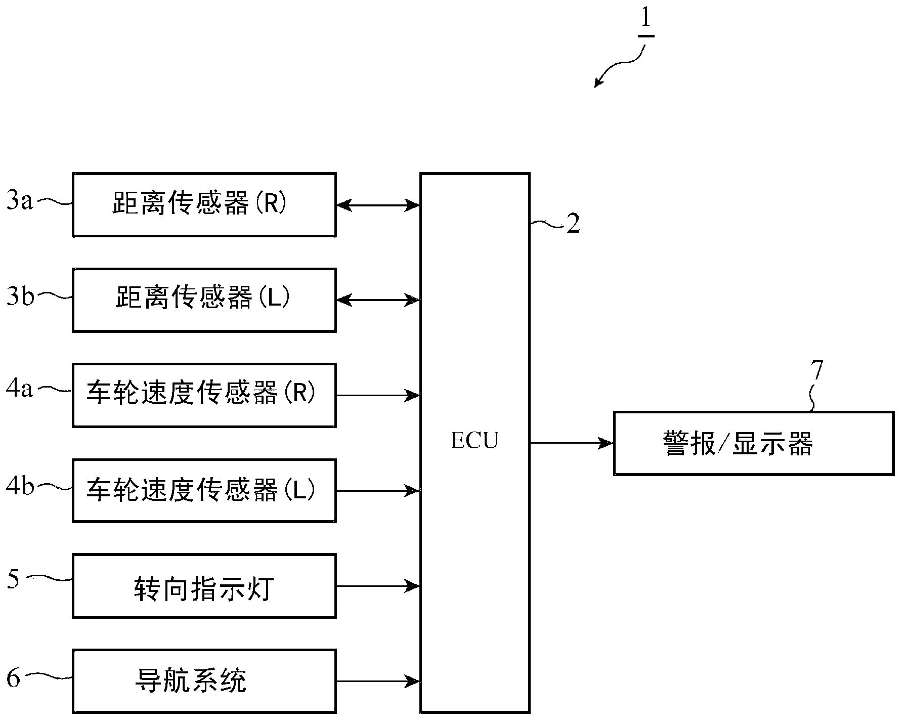
[0026] figure 1 It is a figure which shows the structure of the driving assistance system in this invention. exist figure 1 Among them, the driving assistance system 1 includes a driving assistance device built in an ECU (Electric Control Unit: Electronic Control Unit) 2 that is electronically controlled in the vehicle, distance sensors 3a, 3b, wheel speed sensors 4a, 4b, turn indicators 5, Navigation system 6, and output device 7. The distance sensors 3a and 3b are installed on the left and right sides of the front or rear of the vehicle, emit detection waves and receive reflected waves of the detection waves from the detection target to detect the distance to the detection target sensor. Examples of detection waves include ultrasonic waves, laser light, radio waves, and the like.
[0027] The wheel speed sensors 4a and 4b are sensors provided on the right and left rear wheels of the host vehicle, and detect the wheel speed (the number of pulses corresponding to the rotat...
Embodiment approach 2
[0080] The configuration of the second embodiment is basically the same as that of the first embodiment, but differs from the first embodiment in that the running state determination unit determines that the vehicle meanders, so-called "swaying", as the running state of the own vehicle. Therefore, the structure of the driving assistance device in Embodiment 2 can refer to figure 2 .
[0081] Figure 12 It is a figure for demonstrating the determination process of a running state by the running state determination part 11 of Embodiment 2. The distance data indicating the position of the host vehicle in the width direction of the road corrected by the host vehicle position correcting unit 9 is sequentially input into the traveling state determination unit 11 as time-series information indicating the position of the host vehicle in the direction of the width of the road. , and use the time-series information to determine the driving state of the host vehicle 13 .
[0082] Her...
Embodiment approach 3
[0089] The structure of the third embodiment is basically the same as that of the first embodiment, but differs from the first embodiment in the following point: that is, in the case of frequently observing reflected waves by transmitting ultrasonic waves from ultrasonic sensors installed on the left and right sides of the vehicle once , the vehicle position correction unit sets the transmission sensitivity of the ultrasonic sensor to be higher and the reception sensitivity to be lower, and when the speed of the vehicle is faster than the specified speed, the vehicle position correction unit sets the ultrasonic sensor The transceiver sensitivity is set higher. Therefore, the structure of the driving assistance device in Embodiment 3 can refer to figure 2 .
[0090] Figure 13 It is a diagram for explaining the adjustment of the transmission sensitivity and reception sensitivity of the ultrasonic sensor performed by the host vehicle position correcting unit 9 according to th...
PUM
 Abstract
Description
Claims
Application Information