an energy absorbing device
An energy-absorbing device and energy-absorbing tube technology, applied in the field of safety, can solve problems such as large fluctuations in impact resistance, deformation of longitudinal beams and car bodies, and impact on energy-absorbing effects, and achieve stable energy absorption, stable energy absorption, and simple structure Effect
- Summary
- Abstract
- Description
- Claims
- Application Information
AI Technical Summary
Problems solved by technology
Method used
Image
Examples
Embodiment 1
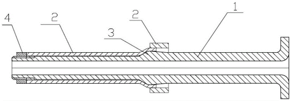
[0022] Embodiment 1: as figure 1 As shown, take an energy-absorbing tube 2 with uniform wall thickness and good plasticity, the cross-sectional shape of the energy-absorbing tube 2 can be circular or polygonal, and the inner wall surface of the energy-absorbing tube 2 is coated with lubricant, so The above-mentioned lubricant can be selected from a dry film lubricant, etc., to ensure that the energy-absorbing tube 2 does not stick to the expansion rod 1 when it expands, and the friction force is stable, thereby ensuring stable expansion resistance.
[0023] One end of the energy-absorbing tube 2 is punched out of a horn-shaped opening with a groove, and the flange is flanged or welded, and a longer expansion rod 1 is inserted from the end of the horn-shaped opening, and a part of the expansion rod 1 is inserted into the suction Inside the energy tube 2, the other part is exposed outside the energy-absorbing tube 2. A convex portion 3 is provided on the outer wall of the expans...
Embodiment 2
[0025] Embodiment 2: Compared with Embodiment 1, the difference is that the energy-absorbing tube 2 is obtained by welding one end of a thick seamless steel pipe and one end of a thin seamless steel pipe, and the expansion rod 1 with the convex part 3 is obtained from One end of the thick seamless steel pipe is inserted, and the outer diameter of the convex part 3 of the expanding rod 1 is smaller than the inner diameter of the thick seamless steel pipe and larger than the inner diameter of the thin seamless steel pipe, so the expanding rod 1 passes through the convex part 3 after being inserted into the thick seamless steel pipe Clamped on one end of the thin seamless steel pipe, the second embodiment of the device is obtained.
Embodiment 3
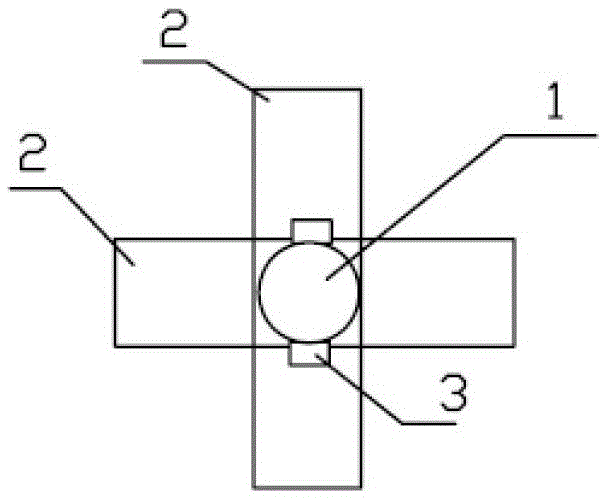
[0026] Embodiment 3: Compared with Embodiment 1, the difference is that, as figure 2 As shown, the energy-absorbing pipe 2 is two identical steel pipes with a rectangular cross-section, one end of one steel pipe is welded to one end of the other steel pipe, and the two steel pipes are vertically arranged, that is, form a "cross" from a top view shape. The expansion rod 1 is inserted from one end of a steel pipe at the cross-shaped intersection area, and the expansion rod 1 has a radially outwardly extending convex portion 3, and another steel pipe is clamped by the convex portion 3 to obtain the present invention. The third implementation.
PUM
 Abstract
Description
Claims
Application Information
 - R&D
- Intellectual Property
- Life Sciences
- Materials
- Tech Scout
- Unparalleled Data Quality
- Higher Quality Content
- 60% Fewer Hallucinations
Browse by: Latest US Patents, China's latest patents, Technical Efficacy Thesaurus, Application Domain, Technology Topic, Popular Technical Reports.
© 2025 PatSnap. All rights reserved.Legal|Privacy policy|Modern Slavery Act Transparency Statement|Sitemap|About US| Contact US: help@patsnap.com


