Manual hole digging support pile prestress anchor cable anchoring structure and construction method of anchoring structure

A technology of prestressed anchor cable and artificial hole digging is applied in excavation, sheet pile wall, foundation structure engineering and other directions, which can solve the problems of complex construction process, waste of cost, ineffectiveness, etc., and achieve simple construction method and cost saving. , the effect of good anchoring effect

Inactive Publication Date: 2012-12-19
CHINA CONSTR SECOND ENG BUREAU LTD
View PDF4 Cites 16 Cited by
  • Summary
  • Abstract
  • Description
  • Claims
  • Application Information

AI Technical Summary

Problems solved by technology

[0003] The purpose of the present invention is to provide an anchoring structure and construction method of artificially excavated support pile prestressed anchor cable, which solves the need to erect a shaped steel beam at the waist of the support pile for integral anchoring of the traditional support pile prestressed anchor cable. The relatively complicated technical problem solved the problem that the prestressed anchor cables of some support piles with steel beams could not play a role because all the support piles could not be guaranteed to be on the same facade in the early stage of construction, resulting in A lot of waste and high cost technical problems

Method used


Image

  • Manual hole digging support pile prestress anchor cable anchoring structure and construction method of anchoring structure
  • Manual hole digging support pile prestress anchor cable anchoring structure and construction method of anchoring structure
  • Manual hole digging support pile prestress anchor cable anchoring structure and construction method of anchoring structure

Examples


Embodiment Construction

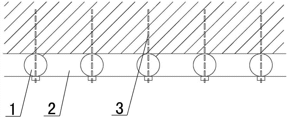
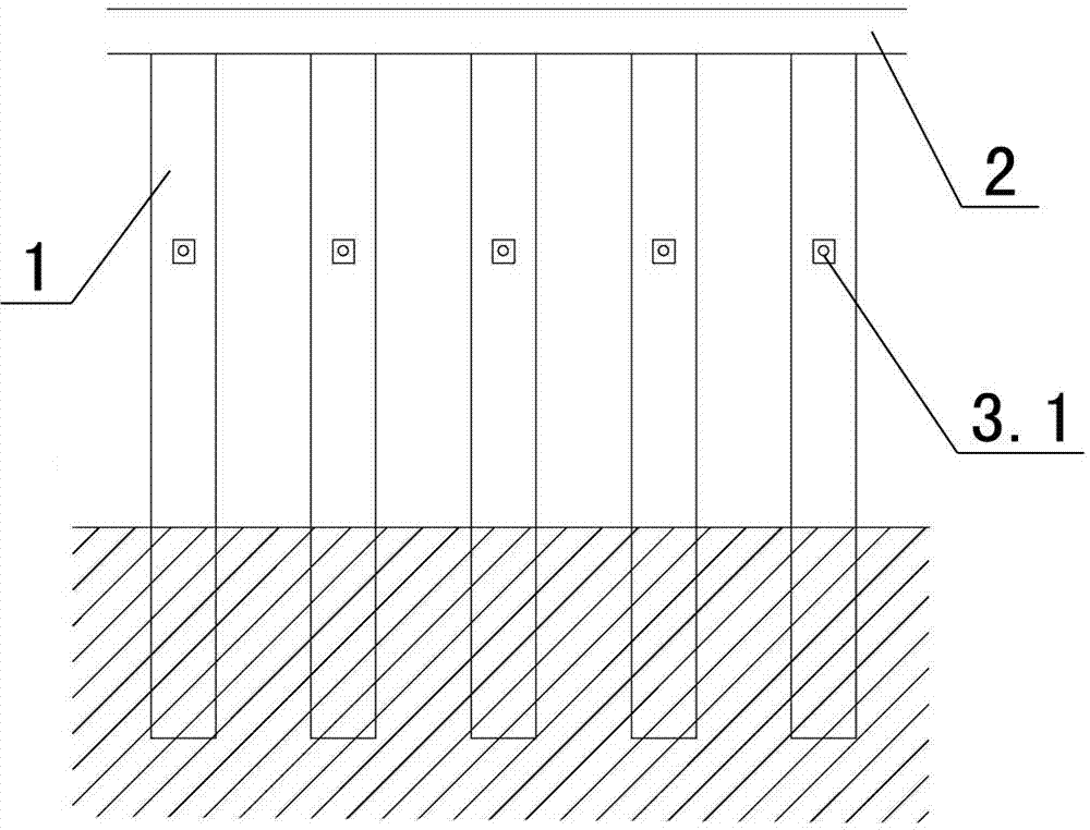
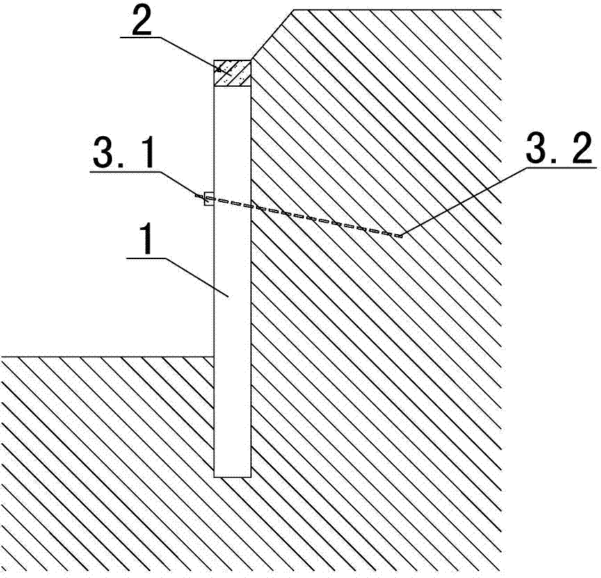
[0043] Examples see Figure 1-3 As shown, a prestressed anchor cable anchoring structure of artificial excavation support piles includes a circle of support piles 1 arranged along the inner side of the foundation pit, a connecting beam 2 arranged on the top of the adjacent support piles, and prestressed anchor cables 3. The prestressed anchor cable is divided into anchor head 3.1 and anchor body 3.2. The support pile 1 has anchor cable holes 4 at the same height in the foundation pit. The anchor body 3.2 passes through the anchor cable hole 4. The anchor body 3.2 The outer end is fixed by the anchor head 3.1, and the inner end of the anchor body 3.2 is anchored into the rock-soil body, and the anchor head 3.1 is located outside the support pile 1.

[0044] see Figure 9 As shown, the anchor head 3.1 is composed of anchorage 3.1.1, anchor pier 3.1.2 and anchor plate 3.1.3, and anchors the prestressed anchor cable on the outside of the support pile.

[0045] The diameter of th...


PUM


Abstract

The invention relates to a manual hole digging support pile prestress anchor cable anchoring structure and a construction method of the anchoring structure. The structure comprises a circle of support piles, connecting beams and a prestress anchor cable, wherein the support piles are arranged along the inner side of a foundation pit, the connecting beams are arranged on the pile tops of the adjacent support piles, the prestress anchor cable is divided into an anchor head and an anchoring body, the support piles are respectively provided with anchor holes at the same height in the foundation pit, the anchoring body passes through the anchor holes, the outer end of the anchoring body is fixed by the anchor head, the inner end of the anchoring body is anchored into a rock soil body, and the anchor head is positioned at the outer side of the support pile. The anchoring structure and the construction method have the advantages that the technical problems that the erection of profile steel beams at the waist parts of the support piles are needed by the traditional support pile anchor cable for integral anchoring, and the construction process is relatively complicated are solved; and the technical problems that during the early-stage construction, all support piles cannot be ensured to be on the same vertical surface, the support pile prestress anchor cable of partial belt type steel beams cannot realize the effect, the great waste is caused, and in addition, the manufacture cost is higher are solved.

Description

technical field [0001] The invention relates to an anchor cable anchorage structure and a construction method of foundation pit support piles. Background technique [0002] In order to ensure the integrity of the force of the foundation pit support piles, a large number of steel beams are erected at the waist of the foundation pit support piles in the market, and then anchored with anchor cables in the soil between the piles. method, its construction is relatively complicated, and the preliminary construction cannot guarantee that all the supporting piles are on the same facade, so some steel beams and anchor cables did not play their due role on the supporting piles during the construction, resulting in A large amount of waste, the higher cost. Therefore, seeking a kind of more effective, simpler support pile anchorage method has become the technical problem that needs to be solved urgently. Contents of the invention [0003] The purpose of the present invention is to p...

Claims


Application Information

Patent Timeline
Patent Type & Authority Applications(China)
IPC IPC(8): E02D17/02E02D17/04E02D5/74
Inventor 端木惠蓉石立国张茅杨先平余德浩
Owner CHINA CONSTR SECOND ENG BUREAU LTD
Why Eureka
Try Eureka