Coupler for clamping shell
A coupling and sandwich technology, which is applied in the field of couplings and can solve problems affecting the service life of rotational molding equipment
- Summary
- Abstract
- Description
- Claims
- Application Information
AI Technical Summary
Problems solved by technology
Method used
Image

Examples
Embodiment Construction
[0026] The present invention will be described in detail below in conjunction with the implementations shown in the drawings, but it should be noted that these implementations are not limitations of the present invention, and those of ordinary skill in the art based on the functions, methods, or structural changes made by these implementations Equivalent transformations or substitutions all fall within the protection scope of the present invention.
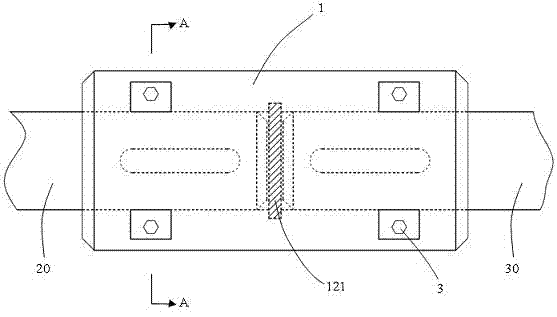
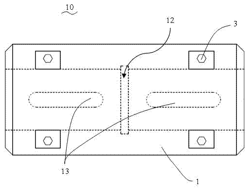
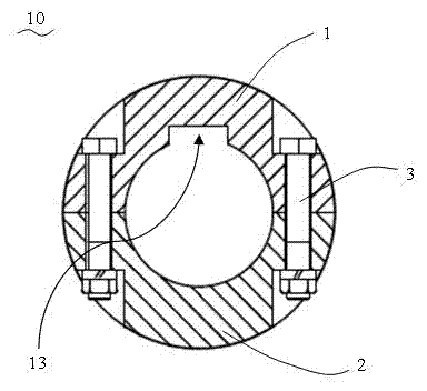
[0027] Please refer to figure 1 , Figure 5 and Figure 7 As shown, in this embodiment, a shell coupling 10 includes: a first shell 1 and a second shell 2 that are split axially and interlocked with each other, and the first shell 1 is provided with four first through holes 11, and the second shell 2 is provided with four second through holes 21, and the first through holes 11 and the second through holes 21 are continuously connected.
[0028] combined reference image 3 and Image 6 As shown, the shell coupling 10 also incl...
PUM
| Property | Measurement | Unit |
|---|---|---|
| Width | aaaaa | aaaaa |
| Thickness | aaaaa | aaaaa |
Abstract
Description
Claims
Application Information