

Display panel and display device
A display panel and substrate technology, applied in optics, instruments, nonlinear optics, etc., can solve problems such as lower transmittance, achieve the effect of improving display quality and light transmittance
- Summary
- Abstract
- Description
- Claims
- Application Information
AI Technical Summary
Problems solved by technology
Method used
Image

Examples
Embodiment Construction
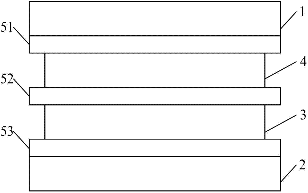
[0029] A display panel provided by an embodiment of the present invention, as attached figure 1 As shown, it may specifically include an upper substrate 1, a lower substrate 2, and a polymer dispersed liquid crystal (PDLC) layer 3 between the two substrates;
[0030] as well as:
[0031] A color filter layer 4 located between the upper substrate 1 and the PDLC layer 3 for displaying primary colors, the color filter layer 4 is filled with electrochromic materials;
[0032] It is used to control the PDLC layer 3 to present different gray scales and the transparent electrode layer (that is, attached figure 1 Indicated by reference numerals 51, 52, 53).
[0033] The realization of the display panel provided by the embodiment of the present invention can effectively improve the light transmittance of the color PDLC display panel, thereby improving the display quality of the color PDLC display panel.
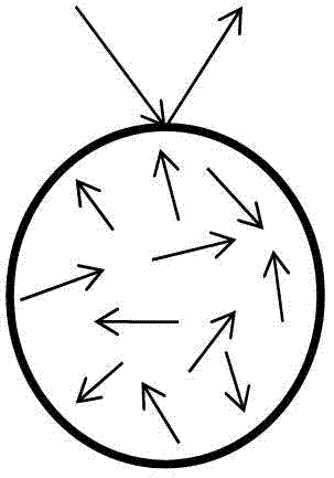
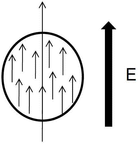
[0034] The working principle of the PDLC layer involved in the embodiment of t...
PUM
 Abstract
Description
Claims
Application Information