Integrated crimping connector
A connector and integrated technology, which is applied in the direction of connection, parts of the connection device, and a device for relieving the stress at the connection of the wire, can solve the problem of not being able to quickly install the connector, and achieve the effect of reliable connection and easy installation
- Summary
- Abstract
- Description
- Claims
- Application Information
AI Technical Summary
Problems solved by technology
Method used
Image
Examples
Embodiment 1
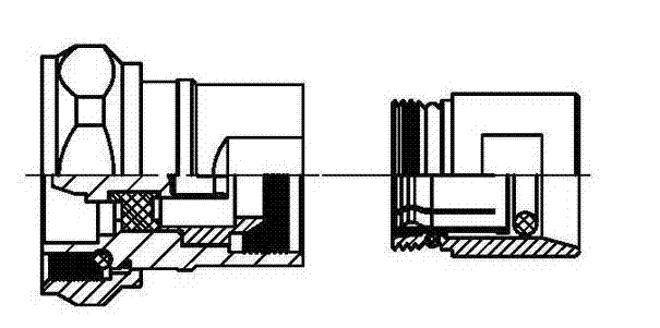
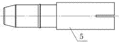
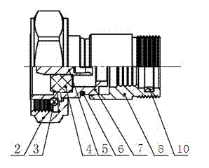
[0036] Such as figure 2 , image 3 with Figure 4 As shown, this embodiment provides an integrated crimp connector, including a screw sleeve 2, an insulator 4, a pin 5, a housing 7 and a cable clamp 8. The insulator 4 is provided in the housing 7, and the insulator 4 Fix the pin 5, an O-ring 3 is arranged between the insulator 4 and the housing 7, and the end of the pin 5 is milled and closed to form an elastic structure. The housing 7 and the cable clamp Two O-rings 6 are arranged between 8 and a flat O-ring 10 is arranged in the cable clamp 8. The housing 7 and the cable clamp 8 are in interference fit.
[0037] This embodiment is an integrated crimping connector. The stripped cable is directly screwed in from the cable clamp 8, and a special tool is used to crimp the integrated connector so that the integrated connector does not clamp the cable from falling off. During the crimping process, the housing 7 moves to the cable clamp 8, and the cable clamp 8 remains stationary...
Embodiment 2
[0039] Such as Figure 5 , Image 6 with Figure 7 As shown, this embodiment provides an integrated crimping connector, including a threaded sleeve 2, an insulator 4, a pin 5, a housing 7 and a cable clamp 8. The insulator 4 is arranged in the housing 7, and the insulator 4 Fix the pin 5, an O-ring 3 is arranged between the insulator 4 and the housing 7, and the end of the pin 5 is milled and closed to form an elastic structure. The housing 7 and the cable clamp There are two O-rings 6 between the 8 and the cable clamp 8 is provided with a flat O-ring 10, the housing 7 and the cable clamp 8 are interference fit, and also includes a rubber front shell 1 and a plastic rear shell 11. The screw sleeve 2 is set in the rubber front housing 1, the cable clamp 8 is set in the plastic rear housing 11, and the plastic rear housing 11 is provided with a sealing ring 12, the A sealing ring 12 is provided between the cable clamp 8 and the plastic rear housing 11.
[0040] This embodiment is ...
Embodiment 3
[0042] Such as Picture 8 with Picture 9 As shown, an integrated crimping connector includes a screw sleeve 2, an insulator 4, a pin 5, a housing 7 and a cable clamp 8. The insulator 4 is provided in the housing 7, and the insulator 4 fixes the The pin 5 is provided with an O-ring 3 between the insulator 4 and the housing 7, and the end of the pin 5 is milled and closed to form an elastic structure. It also includes a rear housing 9, and the cable clamp 8 is arranged at In the rear housing 9, a boss 13 is provided on the inner surface of the cable clamp 8, an O-ring 3 is provided between the housing 7 and the rear housing 9, and a flat O-ring is provided in the rear housing 9 Ring 10, the housing 7 and the rear housing 9 are interference fit.
[0043] In an integrated crimping connector of this embodiment, the stripped cable is inserted from the rear housing 9 so that the cable passes through the inner hole of the cable clamp 8, and the boss 13 of the cable clamp 8 is embedded i...
PUM
 Abstract
Description
Claims
Application Information
 - R&D
- Intellectual Property
- Life Sciences
- Materials
- Tech Scout
- Unparalleled Data Quality
- Higher Quality Content
- 60% Fewer Hallucinations
Browse by: Latest US Patents, China's latest patents, Technical Efficacy Thesaurus, Application Domain, Technology Topic, Popular Technical Reports.
© 2025 PatSnap. All rights reserved.Legal|Privacy policy|Modern Slavery Act Transparency Statement|Sitemap|About US| Contact US: help@patsnap.com


