
Front-end circuit for current input ADC (Analog to Digital Converter)
A front-end circuit and input terminal technology, applied in the direction of analog-to-digital converters, etc., can solve the problems of limiting the speed of the integrator, reducing the speed, and large chip area, so as to improve the input dynamic range and simplify the design.
- Summary
- Abstract
- Description
- Claims
- Application Information
AI Technical Summary
Problems solved by technology
Method used
Image

Examples
Embodiment Construction
[0011] In the following, the specific implementation manners of the present invention will be further described in detail in conjunction with the accompanying drawings of the embodiments, so as to make the technical solution of the present invention easier to understand and grasp.
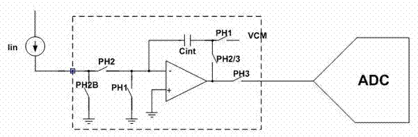
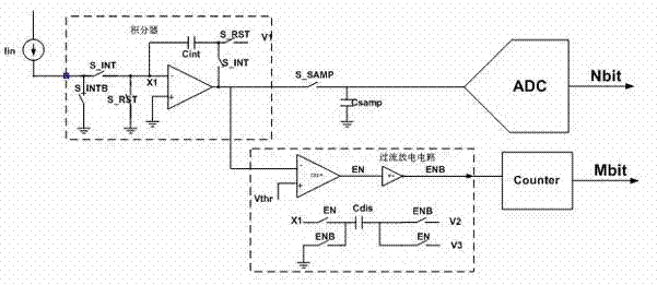
[0012] Such as figure 2 As shown, the front-end circuit of the present invention is based on the architecture of the traditional current input ADC front-end design, and an overcurrent discharge circuit is added. This circuit will pass the detection of the output voltage of the integrator. When the output of the integrator exceeds the threshold voltage Vthr, Discharges the left plate of the integrating capacitor so that the integrator does not exceed the normal operating range. The threshold voltage Vthr is a preset threshold for the integrator to discharge. The overcurrent discharge circuit includes two parts, a detection module and a discharge module, wherein the detection module is at least one...
PUM
 Abstract
Description
Claims
Application Information