Continuous casting mold, method for adjusting taper of continuous casting mold, and continuous casting method

A casting mold and linkage technology, which is applied in the taper adjustment of continuous casting molds and in the field of continuous casting casting molds, can solve problems such as increased maintenance costs, complicated control, and harsh setting environments, and achieves the effect of a simple drive mechanism

Active Publication Date: 2014-10-15
JFE STEEL CORP
View PDF1 Cites 0 Cited by
  • Summary
  • Abstract
  • Description
  • Claims
  • Application Information

AI Technical Summary

Problems solved by technology

However, there are the following problems, that is, (1) the installation environment is bad, (2) the control is complicated due to the need to obtain the tuning of the driving device, (3) the initial investment cost and maintenance cost of the four-point independent control are increased

Method used


Image

  • Continuous casting mold, method for adjusting taper of continuous casting mold, and continuous casting method
  • Continuous casting mold, method for adjusting taper of continuous casting mold, and continuous casting method
  • Continuous casting mold, method for adjusting taper of continuous casting mold, and continuous casting method

Examples


Embodiment 1

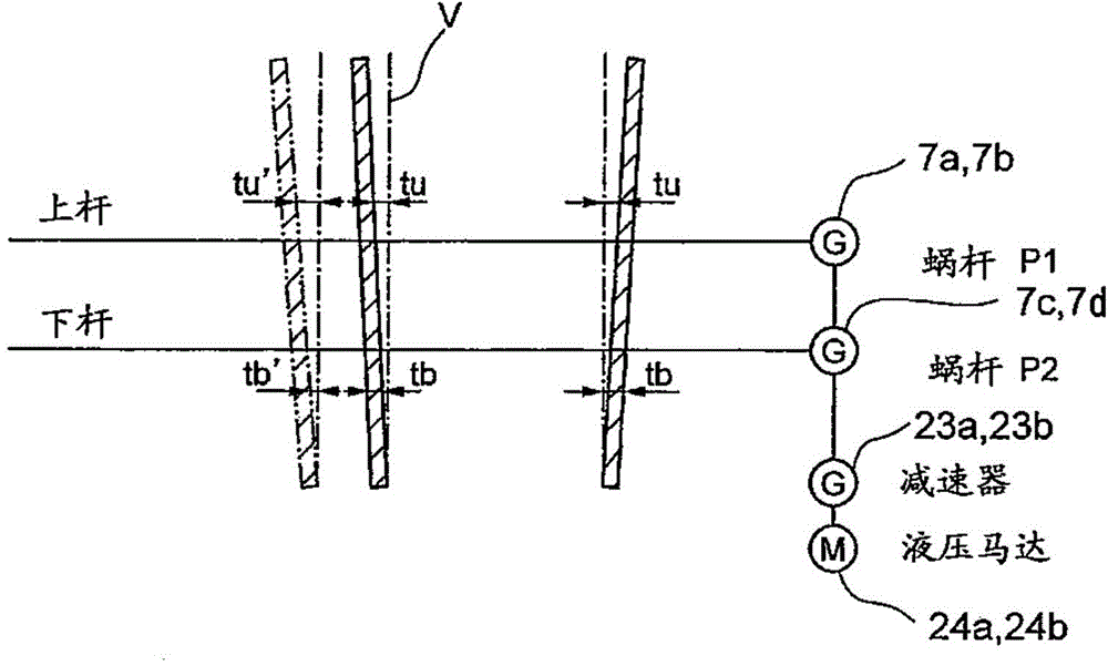
[0045] The pitch of the upper worm on the long side of the movable mold (equal to the lead because it is one thread) is 12.038 mm, and the pitch of the lower worm is 12.000 mm. The optimum taper shape shown in 1 (expressed as long-side taper = difference between upper and lower ends). In addition, the distance between the mold long pieces is set to be slightly larger than the thickness of the slab.

[0046] [Table 1]

[0047] Slab Thickness

Long side taper (difference between upper and lower ends)

220mm thick

2.00mm

235mm thick

2.15mm

260mm thick

2.48mm

300mm thick

3.00mm

[0048] In the comparative example where the taper of the long side was fixed, the taper of the long side was fixed at 2.3 mm (upper end of the short side - short lower edge). In this case, the long-side taper at a thickness of 220 mm is also 2.3 mm.

[0049] Table 2 shows comparative examples in which the long-side taper is fixed.

[0050]...

Embodiment 2

[0053] The casting mold of the example of the present invention and the casting mold of the comparative example were assembled in the continuous casting machine, and the actual machine was used to compare to what extent the maximum casting speed could be increased. Table 3 shows the specifications of the continuous casting machine used. The casting mold of the example of this invention was assembled in the continuous casting machine A, and the casting mold of the comparative example was assembled in the continuous casting machine B.

[0054] [table 3]

[0055]

[0056] Table 4 and Table 5 show the results of the experiments. As evaluation items, it was judged whether or not work was possible in consideration of powder consumption, presence or absence of sand adhering, drawing resistance, and the like. Mark ○ if it can work, and × if it cannot work.

[0057] [Table 4]

[0058] Continuous casting machine A (example of the present invention)

[0059]

[0060]

[006...


PUM


Abstract

A casting mold for continuous casting, a method for adjusting the taper of the casting mold for continuous casting, and a continuous casting method, wherein a first drive mechanism (7a) arranged in the vertical direction of the long side (1a) of the fixed casting mold and The third driving mechanism (7c) can be connected in a synchronous manner, and the second driving mechanism (7b) and the fourth driving mechanism (7d) arranged in the vertical direction of the fixed mold long side (1a) are connected by the second connecting shaft (22b). The first to the fourth drive mechanisms (7a to 7d) are linked to operate by rotating the first and second connecting shafts (22a, 22b) around their axes, and the first to the second The four driving mechanisms (7a-7d) change the inclination angle of the movable mold long side (1b), so that the taper shape of the long side of the mold can be optimized without the connection in the left and right directions, and it is similar to the four-point independent control method. Than can use a simple drive mechanism.

Description

technical field [0001] The present invention relates to a casting mold for continuous casting in which a pair of short sides of a casting mold are replaceably sandwiched between long sides of a pair of casting molds in continuous casting, and a method for adjusting the taper of a continuous casting casting mold using the casting mold for continuous casting and continuous casting methods. Background technique [0002] In order to cast slabs having different thicknesses of slabs, there is known a technique of replacing the short side of the mold on-line (see Patent Document 1). In this on-line replacement technique, one of the long sides of a pair of molds is set as a fixed side, and the other long side of the mold that is opposite to the long side of the fixed side can move freely (that is, make it a movable side). ). A pair of short sides of the mold produced in accordance with the desired slab thickness are sandwiched between the long sides of the fixed side and the movab...

Claims


Application Information

Patent Timeline
Patent Type & Authority Patents(China)
IPC IPC(8): B22D11/05B22D11/04
CPCB22D11/05B22D11/168B22D11/04
Inventor 龟田澄广濑良泰三内藤诚
Owner JFE STEEL CORP
Why Eureka
Try Eureka