
Die plate for resin granulation

A mold plate and granulation technology, which is applied in the field of mold plates for resin granulation, can solve problems such as temperature difference and particle shape deviation

Active Publication Date: 2012-12-26
JAPAN STEEL WORKS LTD
View PDF3 Cites 0 Cited by
  • Summary
  • Abstract
  • Description
  • Claims
  • Application Information

AI Technical Summary

Problems solved by technology

[0018] In addition, in Figure 7 In the case of the existing structure, each of the inlet and the outlet of the heating medium is formed in each area, and the heating medium that performs heat exchange with the respective nozzle hole groups on the inlet side is recirculated with respect to the respective nozzle hole groups on the outlet side , Therefore, the respective nozzle hole groups on the inlet side and the outlet side have a temperature difference between each other, and a deviation occurs in the shape of the particles formed in the same manner as described above.

Method used


Image

  • Die plate for resin granulation
  • Die plate for resin granulation
  • Die plate for resin granulation

Examples


Embodiment

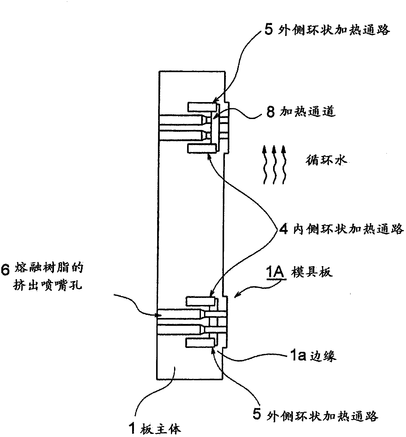
[0042] below, with Figure 1 Preferred embodiments of the mold plate for resin granulation of the present invention will be described together.

[0043] In addition, the same code|symbol is attached|subjected and demonstrated about the same or equivalent part as a conventional example.

[0044] exist figure 1 In the figure, reference numeral 1A denotes a die provided on an unillustrated extruder, that is, a die plate. On the die plate 1A, many extrusion nozzle holes 6 for molten resin are formed in an annular shape. The inner and outer annular heating passages 4 and outer annular heating passages 5 are formed on the inner and outer sides of the cross section of the plurality of nozzle holes 6 .

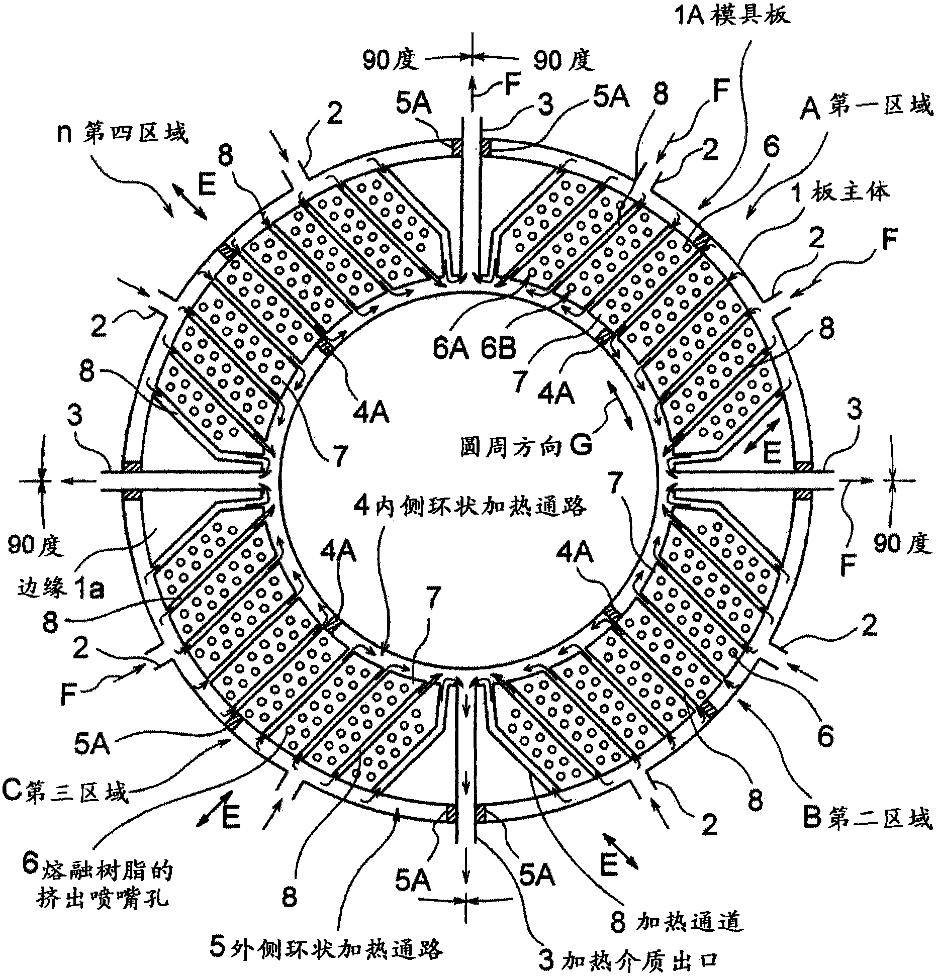
[0045] If the figure 1 The mold plate 1A of is enlarged and observed from the right side, and in the case of n=4 and divided every 90 degrees, it is as follows figure 2 structure as shown.

[0046] exist figure 2 Among them, the reference numeral 1 represents the plate main ...


PUM


Abstract

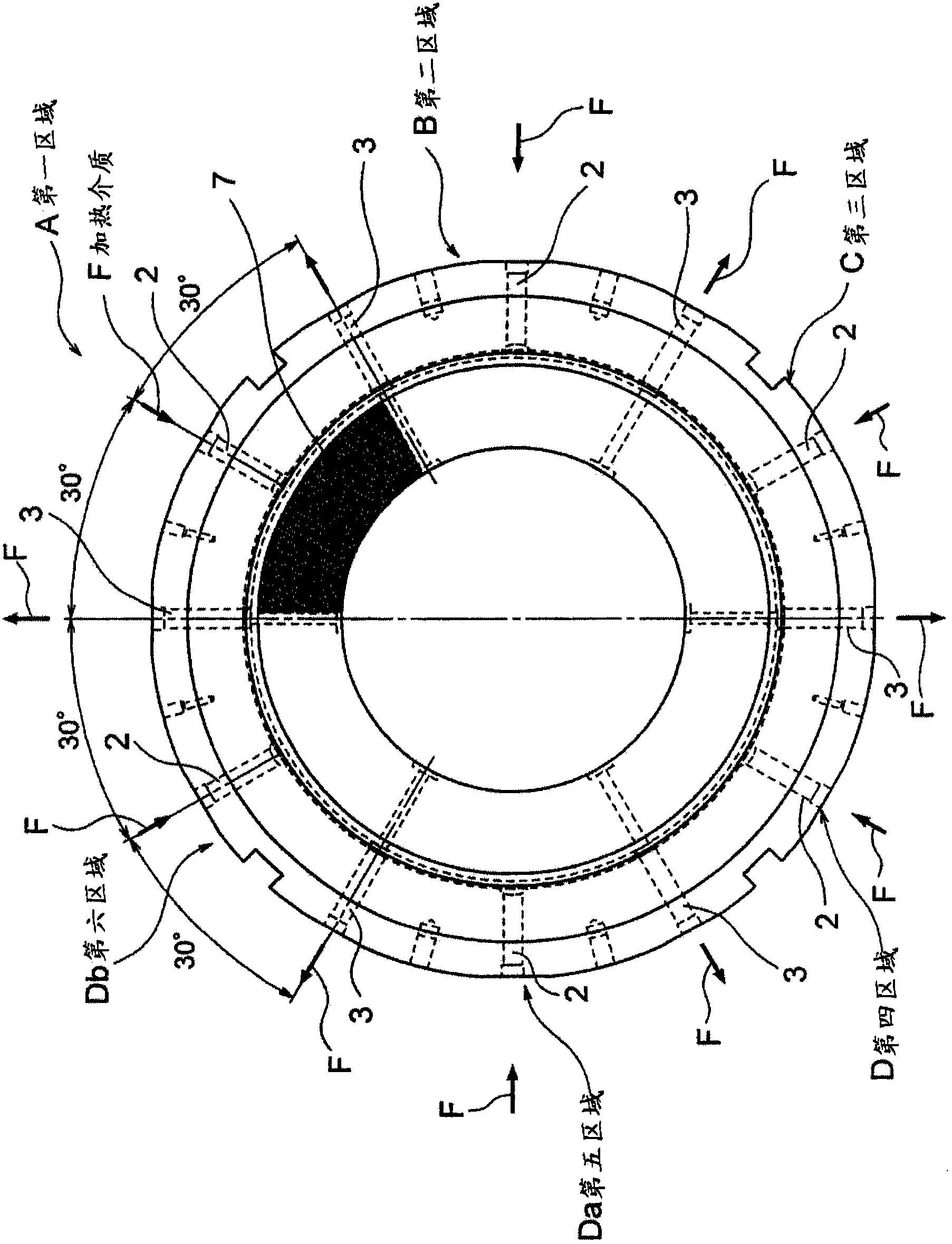
In order to ensure quality of pellets by eliminating temperature differences among extrusion nozzle holes with use of a heating medium flowing through heating channels only once and flowing out through a heating medium outlet, a die plate for resin granulation is provided. In die plate for the resin granulation, a plate main body (1) is divided into regions (A to n) for every 360 / n (n=4, 6, or 8) degrees, or into first to fourth regions (A to D) for every 90 degrees, and an inner annular heating passage (4) and an outer annular heating passage (5) are formed. A heating medium (F) supplied through a heating medium inlet (2) flows through heating channels (8) only once, and then flows out through a heating medium outlet (3) to an outside. Accordingly, the heating medium (F), which has been passed through the heating channels (8) once, does not pass through the heating channels (8), so that the temperature differences among the extrusion nozzle holes (6) can be prevented.

Description

technical field [0001] The present invention relates to a die plate for resin granulation, and more particularly to a new improvement for eliminating the temperature difference of extrusion nozzle holes and maintaining pellet quality by making the heating medium flow only once in the heating channel and then flow out from the heating medium outlet. Background technique [0002] In general, a pelletizing device for plastic pellets is provided downstream of the extruder, and has a die plate for extruding molten resin from a nozzle and a cutter for cutting the resin extruded from the die plate nozzle into pellets. device, but since the surface of the extrusion resin side of the die plate is exposed to the circulating water for conveying the cut pellets, in order to maintain the temperature of the resin extrusion nozzle of the die plate, a built-in device for making steam, heat medium oil, etc. The casing through which the heating medium passes. In order to produce pellets with...

Claims


Application Information

Patent Timeline
IPC IPC(8): B29B9/06B29C48/04B29C48/05B29C48/345
CPCB29C47/0011B29C47/30B29C47/862B29C47/0066B29B9/065B29C48/865B29C48/04B29C48/0022B29C48/345B29C48/05B29B7/826B29B7/582
Inventor 牧田哲生西本贤二住田修桥本知典
Owner JAPAN STEEL WORKS LTD
Learn More