
Working machine

A technology for working machines and working devices, applied in mechanical equipment, earthmoving machines/shovels, fluid pressure actuating devices, etc. The effect of heat balance

Active Publication Date: 2012-12-26
KUBOTA LTD
View PDF5 Cites 11 Cited by
  • Summary
  • Abstract
  • Description
  • Claims
  • Application Information

AI Technical Summary

Problems solved by technology

[0026] However, in this work machine, the main pump is passively controlled when traveling, and the main pump is load-sensitively controlled when the front working device is used. Disadvantages of dividing the discharge oil from the main pump to the travel control valve, the control valve for the boom, the control valve for the arm, and the control valve for the bucket

Method used


Image

  • Working machine
  • Working machine
  • Working machine

Examples


Embodiment Construction

[0109] Hereinafter, embodiments of the present invention will be described with reference to the drawings.

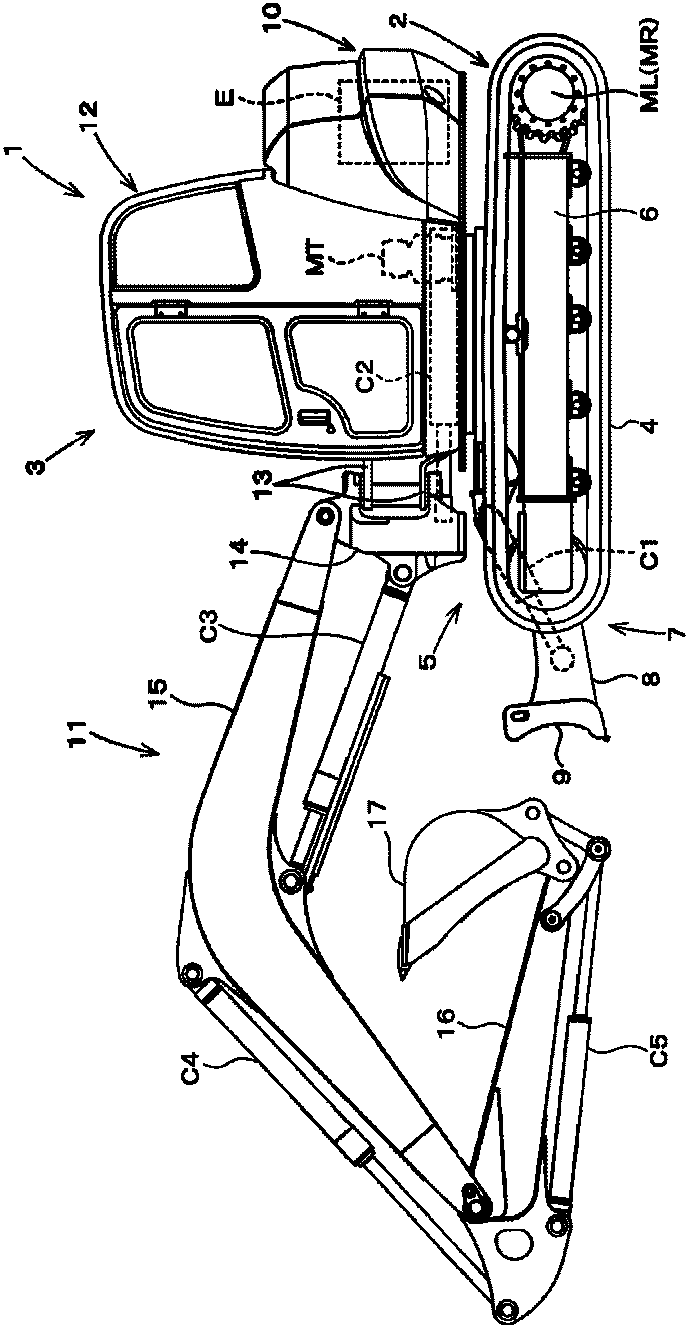
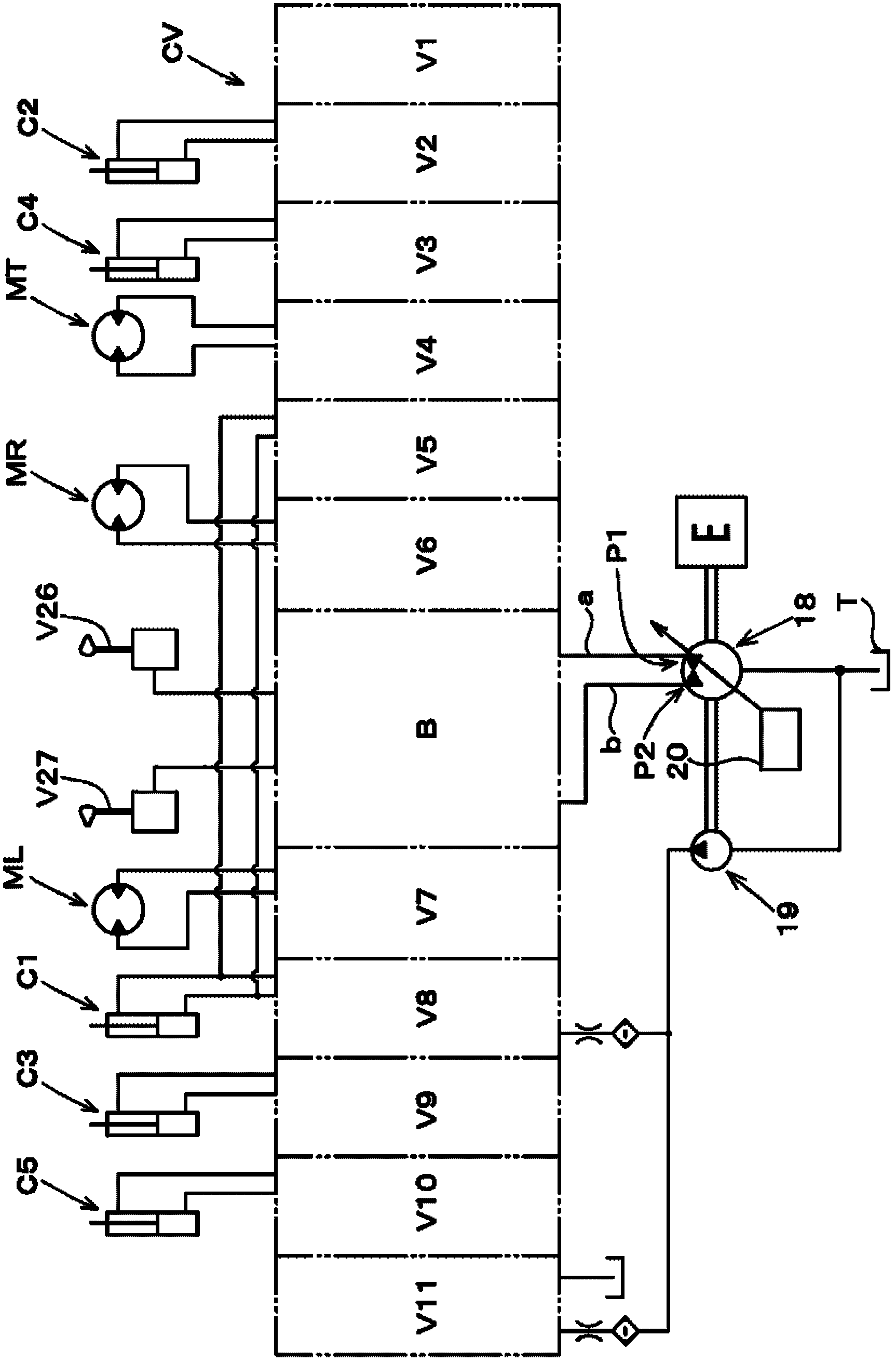
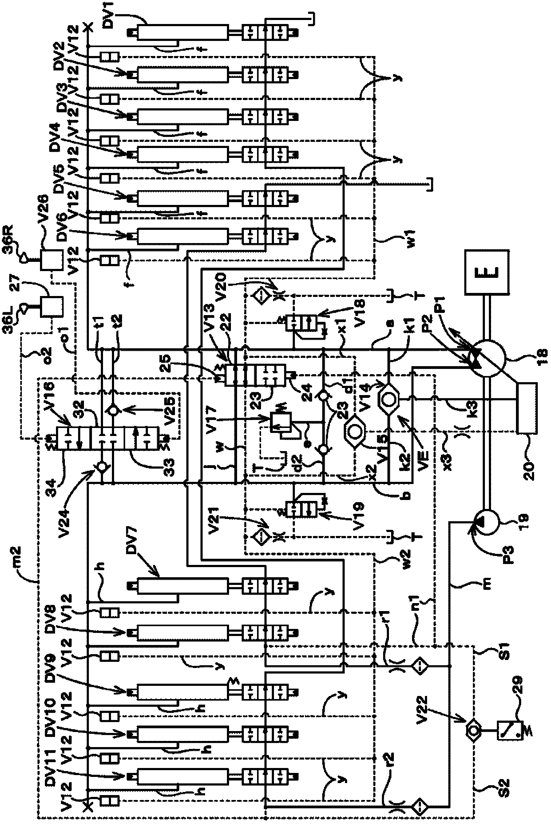
[0110] Figure 1 to Figure 7 represents the first embodiment of the present invention, in figure 1 Among them, reference numeral 1 is a backhoe excavator (working machine). The backhoe excavator 1 is mainly composed of a lower traveling body 2 and a vehicle mounted on the traveling body 2 so that it can rotate around a rotation axis in the up-and-down direction. The upper rotating body 3 constitutes.

[0111] The traveling body 2 has a crawler-type traveling device 5 on the left and right sides of the crawler frame 6, and the crawler-type traveling device 5 is configured such that the endless crawler belt 4 is driven around by traveling motors ML and MR composed of hydraulic motors (hydraulic actuators). Move to the loop.

[0112] A bulldozing device 7 is arranged at the front portion of the crawler frame 6 . The rear end side of the bulldozing device 7 is pivotally...


PUM


Abstract

The invention claims a working machine is set with shunt type of the hydraulic pump working machine it can ensure the steering performance and the working device the working performance and it can well energy saving. The work machine is configured to drive the driving device to drive the front working device at the same time or the drive running device and the operation device for the running independent v13 valve is switched to a current position when it does not drive the front working device to drive the running device when said running independent valve is switched into the independent feeding position. The work machine is set with the load sensitive system the drive running device to drive the front of the working device at the same time and driving travelling device and the front working device when any one of the condition that the load sensitive system are both based on liquid pressure pump discharge pressure and hydraulic executing mechanism of the highest load pressure the difference between the pressure control hydraulic pump is discharged out of the flow.

Description

technical field [0001] The present invention relates to work machines such as backhoe excavators. Background technique [0002] Conventionally, there has been a backhoe described in Patent Document 1 as an operating machine. [0003] In this backhoe excavator, a rotary table is rotatably mounted on a traveling body, a front working device is provided on the front portion of the rotary table, and a bulldozing device is provided on the front portion of the traveling device. [0004] The traveling body has a pair of left and right traveling devices driven by a traveling motor, and the bulldozing device has a scraper that is raised and lowered by a bulldozing hydraulic cylinder. The rotary table is driven to rotate by a rotary motor. [0005] At the front part of the turntable, there is provided a swing bracket that can swing left and right, and the swing bracket is driven to swing left and right by a swing hydraulic cylinder. [0006] The front working device has: a boom sup...

Claims


Application Information

Patent Timeline
IPC IPC(8): E02F9/22
CPCE02F9/2285E02F9/2221E02F9/2292E02F9/2246E02F9/2239E02F9/2296E02F9/22F15B9/08F15B11/17
Inventor 堀井启司
Owner KUBOTA LTD
Learn More