Automatic speed searching device and method for partial stroke test of control valve
A technology for controlling valves and speeds, applied in the direction of valve operation/release devices, valve devices, fluid pressure actuating devices, etc., which can solve the problems of no control valves, etc.
Active Publication Date: 2012-12-26
GENERAL EQUIP & MFG COMPANY INC D B A TOPWORX
7 Cites 3 Cited by
AI-Extracted Technical Summary
Problems solved by technology
There is currently no simple, economical device that can mon...
Abstract
An automatic speed searching device for a partial stroke test of a control valve includes a spool valve operatively connected to a pilot valve and a blocker valve. An electrical module is operatively connected to the pilot valve, a supply of control fluid, and the blocker valve. In an open position of the spool valve, a first control fluid inlet is fluidly connected to a first control fluid outlet, and in a closed position of the spool valve the first control fluid outlet is fluidly connected to a second control fluid outlet. A method of determining an optimum stroke speed includes iteratively powering a main and secondary solenoid in the electrical module and updating parameters to move a control element of the control valve until movement of the control element is within a desired range.
Application Domain
Fluid-pressure actuator testingOperating means/releasing devices for valves +2
Technology Topic
Spool valvePilot valve +3
Image
Examples
- Experimental program(1)
Example Embodiment
[0019] While the following text sets forth a detailed description of exemplary embodiments of the present invention, it should be understood that the legal scope of the present invention is to be defined by the terms of the claims at the end of this patent. The detailed description is exemplary only and does not describe every possible embodiment since describing every possible embodiment would be impractical, if not impossible. Based on reading this disclosure, one skilled in the art will be able to implement one or more alternative embodiments using either current technology or technology developed after the filing date of this patent. Such additional variations still fall within the scope of the claims defining the invention.
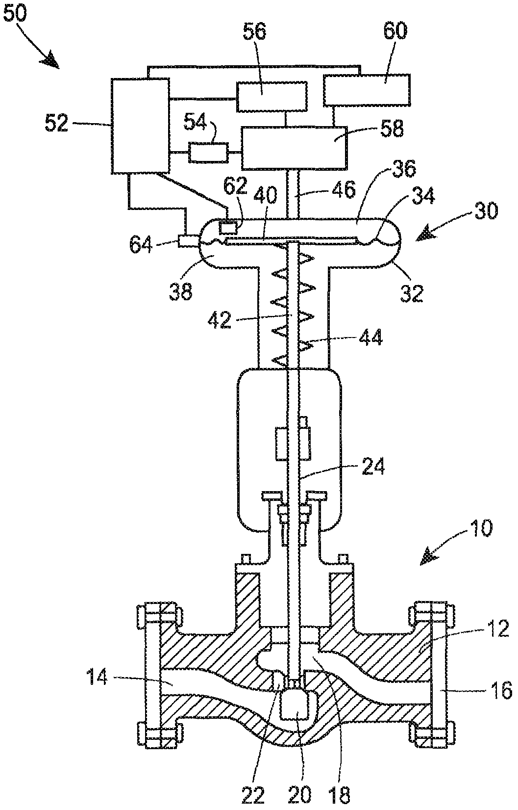
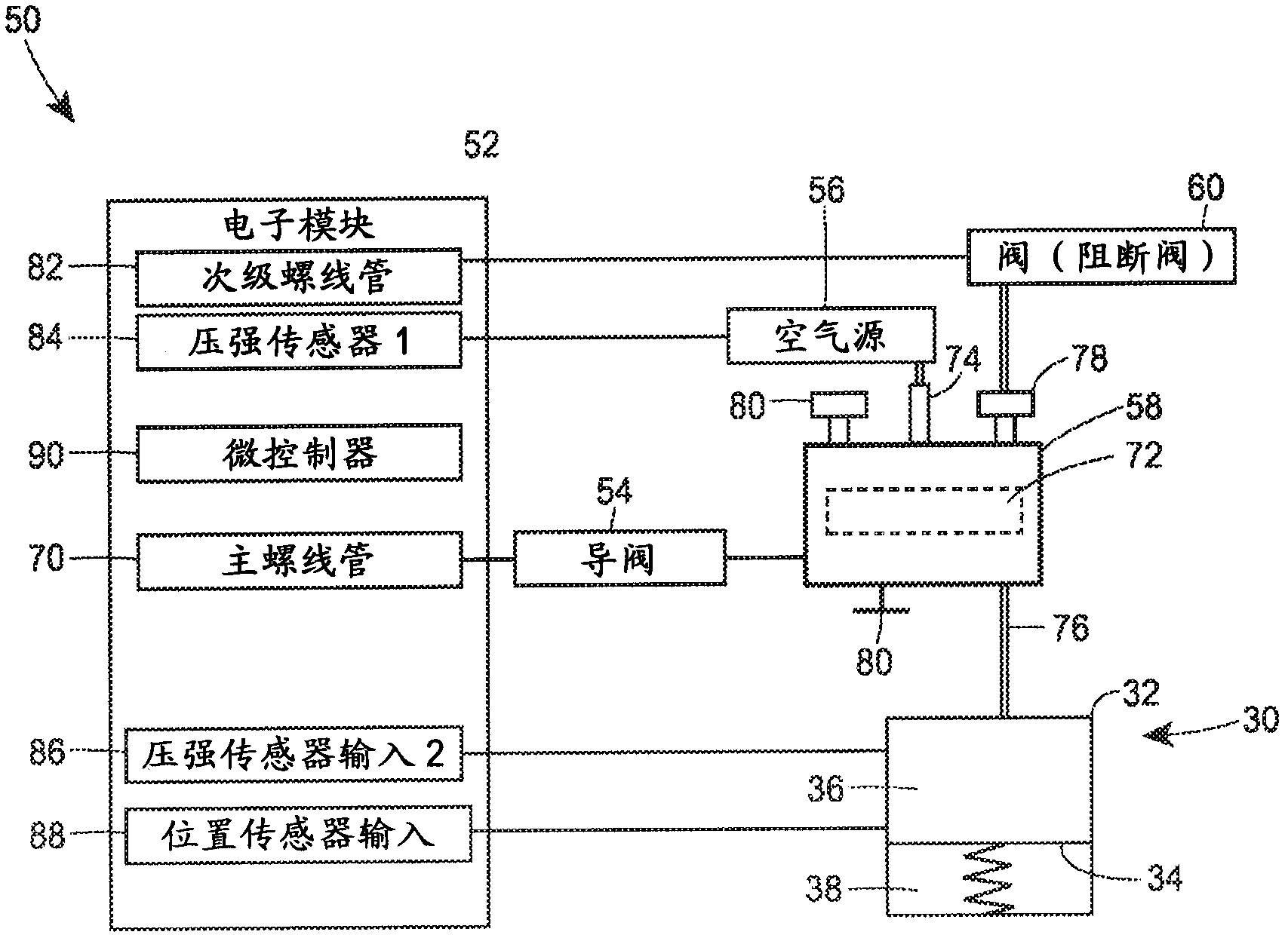
[0020] Control devices for a process control system may include process control devices, such as control valves, dampers, or other variable opening devices, for modulating or controlling fluid flow within the process control system. Although the exemplary embodiments described herein are based on pneumatically controlled valves, other process control devices, such as pumps, electric valves, dampers, etc., are contemplated without departing from the spirit and scope of the present invention. Typically, a control device, such as a control valve assembly, may be located in a conduit or tube to control fluid flow by changing the position of a movable component, such as a valve plug within a control valve, using a coupled actuator. Adjustments to control elements can be used to affect some process conditions to maintain a selected flow rate, pressure, fluid level or temperature.
[0021] The control valve assembly is typically operated by a regulated source of pneumatic fluid pressure, such as air from a factory compressor, although other control fluids may be used. Fluid pressure is introduced into an actuator (eg, a spring and diaphragm actuator for a sliding stem valve or a piston actuator for a rotary valve) through a valve control device that controls the fluid pressure in response to signals received from a process control system. The magnitude of the fluid pressure in the actuator determines the movement and position of the spring and diaphragm or piston within the actuator, thereby controlling the position of the valve stem coupled to the controller element of the control valve. For example, in spring and diaphragm actuators, the diaphragm must work against the biasing spring, placing the control element (ie, the valve plug) in the valve passage between the inlet and outlet of the control valve to alter the process control system flow within. The actuator may be designed such that the increased fluid pressure in the pressure chamber increases or decreases the degree of opening of the control element (eg, direct or reverse motion).
[0022] like figure 1 The control valve 10 of the illustrated system includes relationships involving characteristic loops between output variables, such as valve position, and input variables, such as set points or command signals. This relationship can be called a feature graph, an example of which is in figure 2 shown here, for example, the actuator pressure is plotted against the position of the control element, which is indicated by the position of the valve stem or the actuator stem. like figure 2 As shown, the full scale input-output characteristics of the fluid pressure in the actuator can be plotted over a corresponding range of output positions of the movable components of the control valve 10 . Substituted input variables, such as setpoint command signals, can also be used in the characteristic diagram.
[0023] back figure 1, the control valve 10 includes a valve body 12 containing a fluid inlet 14 and a fluid outlet 16 connected by a fluid passage 18 . The control element or valve plug 20 cooperates with the valve seat 22 to alter fluid flow through the control valve 10 . The valve plug 20 is connected to a valve stem 24 which moves the valve plug 20 relative to the valve seat 22 . The actuator 30 provides force to move the valve plug 20 . The actuator 30 includes an actuator housing 32 surrounding a diaphragm 34 . The diaphragm 34 divides the actuator housing 32 into a first cavity 36 and a second cavity 38 , which are fluidly separated from each other by the diaphragm 34 . Diaphragm 34 is mounted to diaphragm plate 40 which is connected to actuator rod 42 . The actuator stem 42 is connected to the valve stem 24 . Disposed in the second chamber 38 is a spring 44 which biases the diaphragm plate 40 toward the valve seat 22 in this embodiment. In other embodiments, the spring 44 may be located in the first chamber 36 , or the spring 42 may bias the diaphragm away from the valve seat 22 . Regardless, by changing the pressure in the first and second chambers 36 , 38 , the actuator stem 42 moves, which places the valve plug 20 relative to the valve seat 22 to control fluid flow through the valve 10 . exist figure 1 In the embodiment of the present invention, the actuator housing 32 includes a control fluid inlet port 46 for supplying control fluid to the first chamber 36 or removing control fluid from the first chamber 36 to change the control fluid in the first chamber 36 pressure.
[0024] An automatic speed search device 50 is connected to the control fluid inlet port 46 of the actuator 30 . The automatic speed search device 50 controls the flow of fluid into and out of the actuator 30 to find the optimum stroke speed for the partial stroke test. The automatic speed search device 50 includes an electronic module 52 , a pilot valve 54 , a control fluid source, such as a pneumatic supply tank 56 , a spool valve 58 , and a blocking valve 60 . The electronics module 52 receives pressure and position inputs from a pressure sensor 62 and a position sensor 64 connected to or located within the actuator housing 32 . In this embodiment, the pressure sensor 62 measures the control fluid pressure within the first chamber 36 . In other embodiments, the pressure sensor 62 may measure the control fluid pressure or other fluid pressure within the second chamber 38 . Position sensor 64 measures the position of diaphragm 34 , diaphragm plate 40 , actuator stem 44 and/or valve stem 24 . While the position sensor 64 may measure the position of more than one of the diaphragm 34, diaphragm plate 40, actuator stem 44, and valve stem 24, the electronic module 52 only requires the position of one of these components.
[0025] Signals from pressure sensor 62 and position sensor 64 are sent to electronics module 52 where the signals are decoded, and electronics module 52 sends further signals to one of pilot valve 54 , supply tank 56 , and blocking valve 60 or more to actuate the valve stem 24 in the partial stroke test. Signals from pressure sensor 62 and position sensor 64 may be sent to electronics module 52 via a wired connection, wireless connection, or any other electronic connection. Alternatively, pressure sensor 62 and position sensor 64 may send pneumatic, hydraulic or mechanical signals to the electronic module. The electronics module 52 , in turn, sends control signals to the pilot valve 54 , the supply tank 56 and the blocking valve 60 . The control signal may be a control signal sent over a wired or wireless connection. Alternatively, the control signal may be a pneumatic, hydraulic or mechanical signal.
[0026] figure 2 A full stroke characteristic diagram 100 is shown in which the control valve is fully opened from a fully closed position (upstream portion) 102 and in which the control valve is fully closed from a fully open position (downstream portion) 104 . The characteristic diagram illustrates that an initial pressure buildup is required to overcome the momentum and friction or torque of the actuator 30 and/or the control valve 10 before the control valve 10 begins to open and allow flow. When transitioning from the opening movement to the closing movement, momentum and friction may need to be overcome to drive the regulator valve 10 in the other direction. The pressure required to convert the motion can be represented by the vertical path 106 passing between the upstream and downstream paths 102 , 104 . The area between the upstream and downstream paths 102, 104 may be referred to as a dead zone.
[0027] As the control valve or valve performance degrades over time (eg, wear on control elements, wear on valve packing, actuator pressure chamber leakage, etc.), the characteristic graph may change from the initial baseline measurement graph. Such changes over time in the characteristic diagram may reflect operational degradation of the valve due, for example, to friction. The change may prompt repair or replacement of the valve or valve components.
[0028] Baseline characteristic charts are available from manufacturer testing. Alternatively, the baseline characteristic chart can be obtained from user measurements prior to installation or during some initial operation. This baseline chart can be used to help users configure boundaries. For example, using the displayed baseline profile, the user can determine or configure one or more boundaries that serve as deviation thresholds from the baseline against which new profile measurements can be compared. The boundaries can be updated when the user configures the boundaries using the baseline feature graph. Alternatively, the boundary can be drawn using typical computer input devices such as a mouse or light pen. An example of an evaluation system for a valve profile is disclosed in US Patent Publication No. 2008/0004836, assigned to Fisher Controls International. US Patent Publication No. 2008/0004836 is incorporated herein by reference.
[0029] User-configured boundaries using baseline feature graphs may be used to determine whether updated, current, or new feature graphs meet tolerances represented by preset bounds, or if the feature graph indicates a degradation or deviation of one or more features that degrades Or the deviation requires some maintenance operation, such as repairing or replacing the control valve. For example, after configuring one or more boundaries, the current feature graph can be measured and analyzed relative to the configured boundaries to determine whether any graph points violate or exceed the boundaries. The current feature graph can be displayed and overlaid on preconfigured boundaries to determine feature failure, eg, if the current feature graph has points outside the preconfigured boundaries.
[0030] However, during normal on-line operation of a control valve associated with a process control system for controlling at least a portion of the process, normal operation of the control valve may not always drive the entire cycle along the entire valve characteristic curve. This full range traversal or full stroke graph of the input-output characteristics of the control valve may, in many processes, only occur during specific testing of the control valve (eg, during manufacturer testing or factory shutdown). Instead, only partial stroke measurements are possible. In this situation, the extent of one or more of the boundaries may only be configured or adjusted to match the partial stroke extent. Additionally, the graph can still be based on full stroke factory testing, however, only parts of the graph can be used to determine the current valve characteristic boundaries. Alternatively, to determine the boundary conditions of the current partial stroke chart and the current full stroke chart, multiple partial stroke charts may be used to form a baseline chart.
[0031] image 3 The automatic speed search device 50 is shown in detail. The electronics module 52 includes a main solenoid 70 communicatively connected to the pilot valve 54 . The main solenoid 70 controls the configuration of the spool valve 58 by sending a command signal to the pilot valve 54 , which in turn places the spool valve 58 . In one embodiment, the command signal sent from the main solenoid 70 is an electrical signal and the signal sent from the pilot valve 54 to the spool valve 58 is a pneumatic or hydraulic signal. In other embodiments, the signal from the pilot valve 54 may also be an electrical signal. Spool valve 58 includes a slidable piston 72 that moves in response to a signal from pilot valve 54 . The spool valve 58 also includes a control fluid inlet port 74 , a first control fluid outlet port 76 and a second control fluid outlet 78 . The spool valve 58 may also include one or more valve plugs 80 .
[0032] The electronics module 52 may also include a secondary solenoid 82 communicatively connected to the blocking valve 60 . Secondary solenoid 82 sends an electrical signal to block valve 60 to open or close block valve 60 . The first pressure sensor 84 measures the pressure within the supply tank 56, while the second pressure sensor input 86 is input from the pressure sensor 62 ( figure 1 ) receives a pressure signal indicative of the fluid pressure in the actuator 30 . Position sensor input 88 is derived from position sensor 64 ( figure 1 ) receives a position sensor signal indicative of the position of the actuator stem 42 and/or the valve stem 24 . processor 90 according to Image 6 and 7 The logic diagram shown handles pressure and position inputs and controls primary and secondary solenoids 70 , 82 to selectively place pilot valve 54 , spool valve 58 and block valve 60 .
[0033] like Figure 4 As shown, the electronics module 52 configures the spool valve 58 to control fluid from the supply tank 56 into the actuator 30 by instructing the pilot valve 54 to place the piston 72 to fluidly connect the control fluid inlet port 74 and the first control fluid outlet port 76 . As control fluid flows from supply tank 56 through spool valve 58 and into actuator 30, the control fluid pressure in first chamber 36 of the actuator will increase, causing diaphragm 34 and diaphragm plate 40 to move toward control valve 10 ( figure 1 ). Accordingly, the actuator stem 42 and valve stem 24 will also move toward the control valve 10, causing the valve plug 20 to move away from the valve seat 22, with the result that more fluid flows through the control valve.
[0034] like Figure 5 As shown, the electronics module 52 may also configure the spool valve 58 to control fluid flow out of the actuator 30 by instructing the pilot valve 54 to place the piston 72 to fluidly connect the second control fluid outlet port 78 and the first control fluid outlet port 76 (In this case fluid flows out of the actuator 30 and into the spool valve 58). As the control fluid flows from the actuator 30 through the spool valve 58 and into the blocking valve 60, the control fluid pressure in the first chamber 36 of the actuator will decrease, causing the diaphragm 34 and diaphragm plate 40 to move away from the control valve 10 ( figure 1 ). Accordingly, the actuator stem 42 and valve stem 24 will also move away from the control valve 10, causing the valve plug 20 to move away from the valve seat 22, with the result that more fluid flows through the control valve. In this configuration, control fluid is fluidly connected from supply tank 56 to valve plug 80 , preventing control fluid from flowing into actuator 30 . Furthermore, in this configuration, the blocking valve 60 ultimately controls the rate of fluid flow out of the actuator 30 .
[0035] The processor 90 transmits signals in the form of electrical pulses to the primary and secondary solenoids 70, 82 to operate the primary and secondary solenoids 70, 82 in a step-by-step fashion. In this way, processor 90 can precisely and progressively cause control fluid to flow into or out of actuator 30 by controlling the position of piston 72 and blocking valve 60 . Accordingly, the actuator rod 42 and the valve rod 24 also move progressively.
[0036] When performing a partial stroke test, the automatic speed search system 50 determines the optimum stroke speed for the partial stroke test by executing a series of software instructions on the processor 90, regardless of actuator type, actuator size, or control fluid pressure . Accordingly, the automatic speed search system 50 disclosed herein is versatile (eg, for a virtually infinite combination of actuator types, actuator sizes, and control fluid pressures). Furthermore, the disclosed automatic speed search system 50 can be retrofitted on existing control valves.
[0037] In general, once it is determined to move the valve from fully open to fully closed, or vice versa, at full speed, the automatic speed search system 50 iteratively determines the optimal pulse width for the partial stroke test (eg, at reduced speed and/or partial stroke length) . Once the optimum stroke speed is determined, the automatic speed search system performs a partial stroke test without the need for limit switches, which are required by prior art positioners. Furthermore, the automatic speed search system 50 disclosed herein can be used as a simple positioner in a control valve that does not have a positioner. Compared to known locators, the disclosed automatic speed search system 50 is simpler in structure and more durable than known locators.
[0038] The automatic speed search system 50 disclosed herein repeatedly searches for the optimum pulse width for partial stroke testing by executing a software program on the processor 90 . A software program can use a series of logical instructions such as Image 6 and 7 logic shown. Image 6 The logic diagram of is an example of the logic of the speed search routine used to perform the partial stroke test as the valve plug or control element moves from the open position towards the closed position. Similar to this, Figure 7 The logic diagram of is an example of the logic of the speed search routine used to perform a partial stroke test when the valve plug or control element is moved from the closed position towards the open position.
[0039] now go to Image 6 , showing an example of partial stroke test logic 200 for controlling movement of an element from an open position to a closed position. Initially, certain parameters are set for the system. For example, enter the full stroke length (L), the target time for the full motion (T), and the number of steps (N). In the case of target time (T) and number of steps (N), these raw parameters may be user-selectable, or in the case of, for example, full stroke length (L), the raw parameters may be based on manufacturer's data or actual measurements. T/N seconds per stroke step (B). Processor 90 begins with the initial inputs discussed above. At step 208, the primary solenoid 70 is energized and the secondary solenoid 82 is de-energized to place the control element or valve plug 20 in the fully open position. The main solenoid 70 turns off power at step 210 and measures the time (t 0 ), where t 0 Defined as the time for the control element or valve plug 20 to be impacted from the fully open position to the fully closed position at full or maximum speed. As mentioned above, t 0 Can be determined from manufacturer's data or initial measurements performed after valve installation, no need to measure t for each test 0. once t 0 measurand (or input from manufacturer data), t 0 remains unchanged unless the operator determines t 0 should be remeasured. At step 212, the processor 90 sets the stroke speed coefficient (X) equal to t 0 /N, the stroke speed has a minimum value (X min = 0) and the maximum value (X max =B). At step 213, the primary and secondary solenoids 70, 82 are energized to move the control element or valve plug 20 to the fully open position in preparation for the partial stroke test. At step 214 , the processor 90 instructs the main solenoid 70 to cut power so that the fluid source 56 is cut off from the actuator 50 . At step 215, processor 90 instructs secondary solenoid 82 to de-energize for X seconds, and at step 216, processor 90 instructs secondary solenoid 82 to energize for Y=B-X seconds. In this way, the control fluid is gradually released from the actuator 50 through the blocking valve 60 . Thus, the control element or valve plug 20 is also moved in a stepwise manner. Before step 218, steps 215 and 216 are repeated N/2 times. In other embodiments, steps 215 and 216 may be performed more or less than N/2 times. After performing steps 215 and 216 N/2 times, the position of the control element 20 is determined from the position signal of the position sensor 88 at step 218 , and the position sensor 88 provides the position signal to the controller 90 . A determination is made at step 220, if the control element 20 moves beyond L/2, the controller 90 sets X at step 224 max =X and X=(X min +X max )/2. Thereafter, before moving to step 218, steps 215 and 216 are repeated N/2 times again. However, if at step 220 the control element 20 has not moved beyond L/2, the processor 90 proceeds to step 226. At step 226, if the control element 20 has moved less than L/4, at step 228 the processor 90 sets X min =X and X=(X min +X max )/2. Thereafter, before moving to step 218, steps 215 and 216 are repeated N/2 times again. However, if at step 226 the actuator rod has moved beyond L/4, then by definition, the actuator movement is in the range of L/2 to L/4. This range is considered sufficient for defining the optimal pulse speed or stroke speed coefficient, which is defined as X at step 230 .
[0040] now go to Figure 7 , showing an example of the partial stroke test logic 300 from the closed position to the open position. Initially, certain parameters are set for the system. For example, enter the full stroke length (L), the target time for the full motion (T), and the number of steps (N). In the case of target time (T) and number of steps (N), these raw parameters may be user-selectable, or in the case of, for example, full stroke length (L), the raw parameters may be based on manufacturer's data or actual measurements. T/N seconds per stroke step (B).
[0041] Processor 90 begins with the initial input discussed above. At step 308, the primary solenoid 70 is energized and the secondary solenoid 82 is de-energized to place the control element or valve plug 20 in a fully closed position. The main solenoid 70 is energized at step 310 to measure the time (t 0 ), where t 0 Defined as the time for the control element or valve plug 20 to be impacted from the fully closed position to the fully open position at full or maximum speed. As mentioned above, t 0 Can be determined from manufacturer's data or initial measurements performed after valve installation, no need to measure t for each test 0. once t 0 measurand (or input from manufacturer data), t 0 remains unchanged unless the operator determines t 0 should be remeasured. At step 312, the processor 90 sets the stroke speed coefficient (X) equal to t 0 /N, the stroke speed has a minimum value (X min = 0) and the maximum value (X max =B). At step 313, the primary and secondary solenoids 70, 82 are de-energized to move the control element or valve plug 20 to the fully closed position in preparation for the partial stroke test. At step 314 , the processor 90 instructs the main solenoid 70 to energize so that the fluid source 56 is connected to the actuator 50 . At step 315, the processor 90 instructs the main solenoid 70 to energize for X seconds, and in step 316, the processor 90 instructs the main solenoid 70 to de-energize for Y=B-X seconds. In this way, the control fluid gradually flows into the actuator 50 . Thus, the control element or valve plug 20 is also moved in a stepwise manner from the closed position to the open position. Before step 318, steps 315 and 316 are repeated N/2 times. In other embodiments, steps 315 and 316 may be performed more or less than N/2 times. After performing steps 315 and 316 N/2 times, the position of the control element 20 is determined from the position signal of the position sensor 88 at step 318 , and the position sensor 88 provides the position signal to the controller 90 . A determination is made at step 320, if the control element 20 moves beyond L/2, the controller 90 sets X at step 324 max =X and X=(X min +X max )/2. Thereafter, before moving to step 318, steps 315 and 316 are repeated N/2 times again. However, if at step 320 the control element 20 has not moved beyond L/2, the processor 90 proceeds to step 326. At step 326, if control element 20 has moved less than L/4, at step 328 processor 90 sets X min =X and X=(X min +X max )/2. Thereafter, before moving to step 318, steps 315 and 316 are repeated N/2 times again. However, if at step 326 the actuator rod has moved beyond L/4, then by definition the actuator movement is in the range L/2 to L/4. This range is considered sufficient for defining the optimal pulse speed or stroke speed coefficient, which is defined as X at step 330 .
[0042] The accuracy of the speed control is determined by the number of steps and the response time of the solenoid valve. Accuracy can also be increased by adding algorithms, such as PID control, to processor 90 .
[0043] Figure 8 One embodiment of the spool valve 58 is described. Similar structures can be used for blocking valve 60 . The spool valve 58 includes a valve body 92 including a central bore 93 fluidly connected to the valve plug 80 , a control fluid inlet port 74 , a first control fluid outlet port 76 and a second controller fluid outlet port 78 . A perforated sleeve 94 is provided in the central hole 93 , and the slidable piston 72 is provided in the perforated sleeve 94 . The perforated sleeve 94 includes a plurality of openings 95 scattered around the edges of the perforated sleeve 94 . Opening 95 allows control fluid to flow between control fluid inlet and outlet ports 74 , 76 , and 78 . The perforated sleeve 94 may include a plurality of seals, such as an O-ring 96 that seals against the inner surface of the central bore 93 . O-rings 96 can separate the plurality of openings 95 into different groups, and the O-rings 96 can prevent cross flow between the various groups of openings 95 outside the perforated sleeve 94 . Spacers 97 and/or seals 98 may be provided at either end of the perforated sleeve 94 to place and seal the perforated sleeve 94 within the central bore 93 . The slidable piston 72 moves within the perforated sleeve in response to input from the pilot valve 54 to fluidly communicate two of the control fluid inlet port 74, the first control fluid outlet port 76 and the second control fluid outlet port 78, Fluid flow through the spool valve 58 is thereby controlled, as described above.
[0044] The automatic speed search device disclosed herein advantageously determines the optimum stroke speed without the need for positioners or limit switches. By repeatedly searching for stroke speed using electrical pulses to control the movement of the actuator rod in a step-by-step fashion, the automatic speed search device disclosed herein quickly determines the optimal stroke speed for partial stroke testing, regardless of the type or size of actuator .
[0045] Numerous modifications and alternative embodiments of the present invention will be apparent to those skilled in the art in view of the foregoing description. Therefore, these descriptions are to be interpreted as exemplary only, and for the purpose of teaching those skilled in the art the best mode for carrying out the invention. The details of this disclosure may be changed without departing from the spirit of the invention, with exclusive rights reserved to all variations falling within the scope of the claims.
PUM


Description & Claims & Application Information
We can also present the details of the Description, Claims and Application information to help users get a comprehensive understanding of the technical details of the patent, such as background art, summary of invention, brief description of drawings, description of embodiments, and other original content. On the other hand, users can also determine the specific scope of protection of the technology through the list of claims; as well as understand the changes in the life cycle of the technology with the presentation of the patent timeline. Login to view more.