Method and apparatus for performing diagnostics in a control loop of a control valve

a technology of control valve and control loop, which is applied in the direction of ignition automatic control, servomotors, instruments, etc., can solve the problems of contamination partially or completely plugging the primary orifice or nozzle, the inlet and outlet seals of the i/p converter may fail, and the control valve may be degraded or disabled

Inactive Publication Date: 2005-10-11
FISHER CONTROLS INT LLC
View PDF13 Cites 35 Cited by
  • Summary
  • Abstract
  • Description
  • Claims
  • Application Information

AI Technical Summary

Problems solved by technology

Conventional positioners have components that are susceptible to various control fluid leaks or blockages that may degrade or disable operation of the control valve.
Consequently, when such air is used as the control fluid, the contaminants may partially or completely plug the primary orifice or nozzle.
In addition, the seals provided at the inlet and outlet of the I / P converter may fail.
Such blockages or leaks may slowly degrade the performance of the control valve, resulting in inefficiencies, or may cause complete failure of the control valve.
In either event, it is difficult to determine that the positioner is the cause of the fault, let alone to determine the specific location of the fault within the positioner.
Similarly, leaks may develop in the actuator housing or blockages may form in the connections between the spool valve and the actuator that may degrade control valve performance or cause failure.
For example, a leak may form between the upper or lower actuator chamber and atmosphere, or a piston ring may fail causing leakage from one chamber to the other.
Such leaks may develop over time and, in a noisy plant environment, may go unnoticed until the valve no longer operates.

Method used


Image

  • Method and apparatus for performing diagnostics in a control loop of a control valve
  • Method and apparatus for performing diagnostics in a control loop of a control valve
  • Method and apparatus for performing diagnostics in a control loop of a control valve

Examples


Embodiment Construction

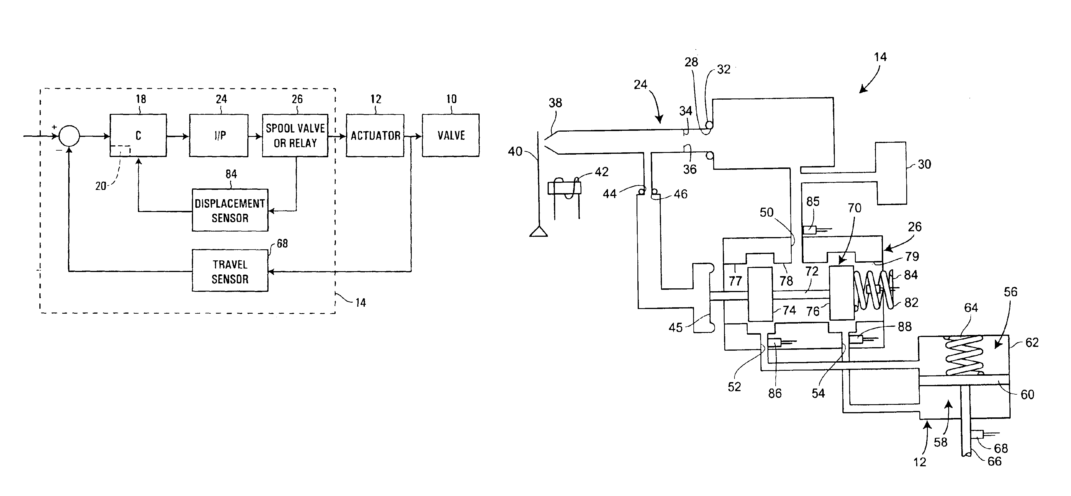
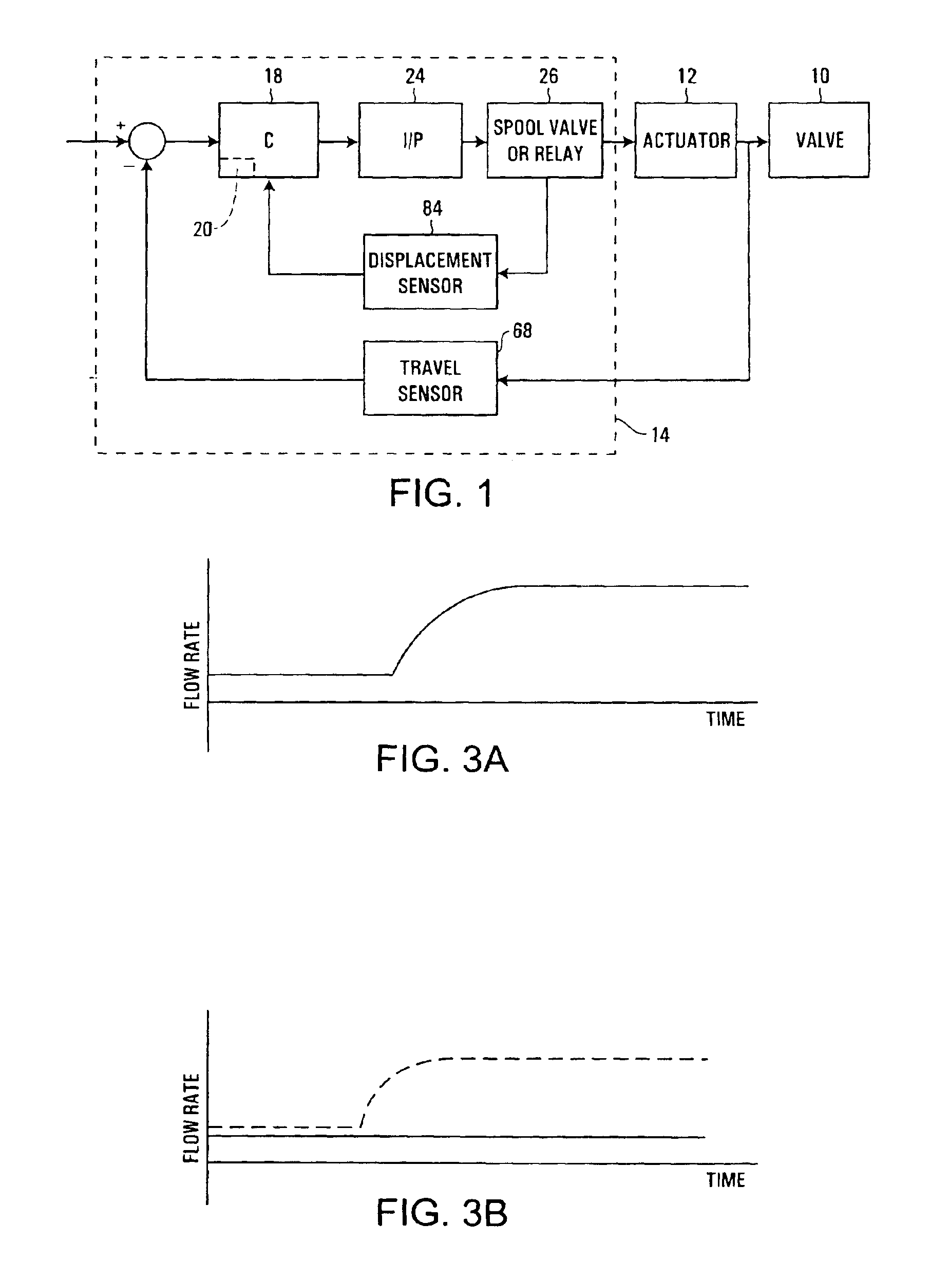
[0014]A positioner 14 is schematically illustrated in FIG. 1 connected to an actuator 12. The actuator 12 is mechanically coupled to a valve body 10, which controls the flow of a process fluid through a conduit, such as a pipe (not shown). The positioner 14 includes a processor 18 having a memory 20, an I / P converter 24, second stage pneumatics (such as spool valve 26), a control fluid valve assembly displacement sensor 84, and a valve travel sensor 68, collectively referred to herein as a control loop. A reference signal, such as a command signal from a process controller, is provided to the positioner 14 and represents a desired actuator position. The positioner 14 compares the reference signal to the actual actuator position provided by the travel sensor 68 and forwards an error signal to the processor 18. The processor then generates an electronic I / P drive signal based on the error signal and feedback from the displacement sensor 84.

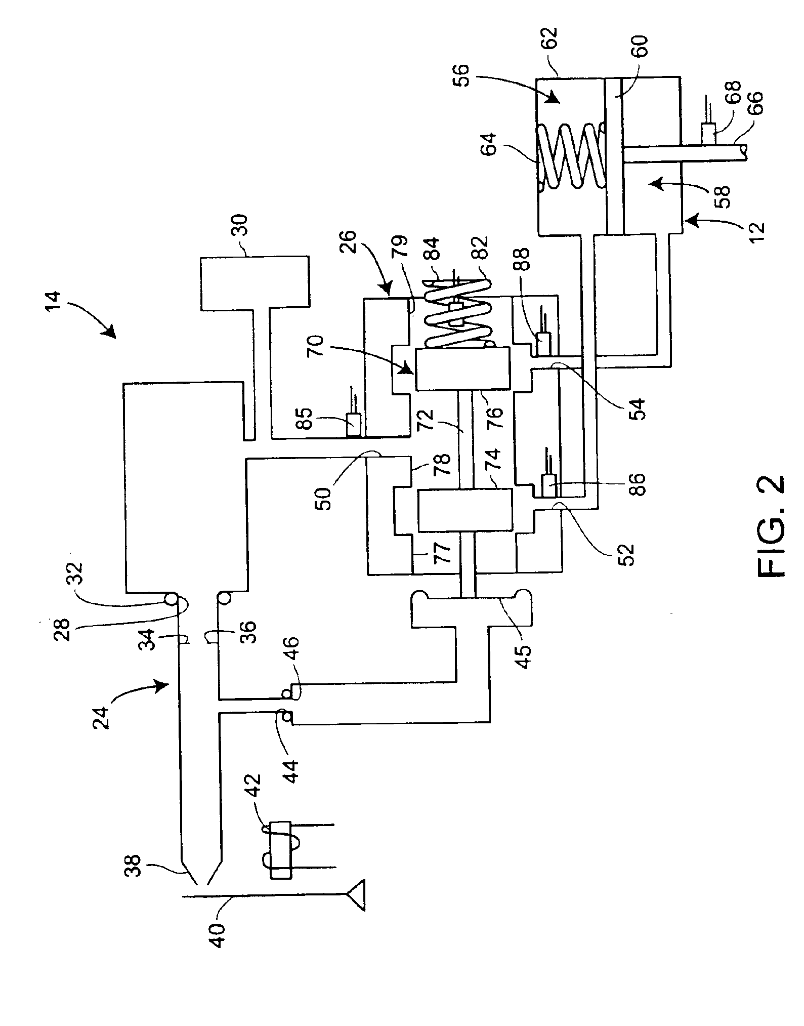
[0015]As shown in greater detail in FIG. 2, t...


PUM


Abstract

Method and apparatus for performing diagnostics in a pneumatic control loop for a control valve. Pressure and displacement sensors normally provided with a positioner are used to detect operating parameters of the control loop. A processor is programmed to receive feedback from the sensors and generate fault signals according to a logic sub-routine. The logic sub-routine may include calculating mass flow of control fluid through spool valve outlet ports and comparing other operating parameters of the control fluid to detect leaks and blockages in the control loop. Once a fault is detected, the location of the root cause of the fault may be identified by characterizing operating parameters of the control loop at the time of the fault.

Description

CROSS-REFERENCE TO RELATED APPLICATION[0001]This application is a divisional of prior application No. 10 / 139,008, filed May 3, 2002 now U.S. Pat. No. 6,678,584.FIELD OF THE INVENTION[0002]The present invention generally relates to control valves and, more particularly, to methods and apparatus for calculating fluid flow characteristics and performing diagnostics on control loop components for a control valve.BACKGROUND OF THE INVENTION[0003]Control valves are used to regulate process fluid flow through a pipe or conduit. Such valves typically include a throttling element disposed in the process fluid flow path and connected to an actuator. While various types of actuators are known, many control valves use a pneumatic actuator which uses air, natural gas, or other fluid under pressure to adjust the position of the actuator. In a spring and diaphragm actuator, for example, a spring applies a force to one side of the actuator while fluid pressure is controlled on an opposite side of t...

Claims


Application Information

Patent Timeline
Patent Type & Authority Patents(United States)
IPC IPC(8): F15B13/00F15B19/00F15B13/04F15B9/08G05B23/02G05D16/20
CPCF15B13/0402F15B19/005G05B23/0235G05B23/0278G05D16/2093G05D16/2097
Inventor JUNK, KENNETH W.LATWESEN, ANNETTE L.
Owner FISHER CONTROLS INT LLC
Why Eureka
Try Eureka