Motorized retractor

a motorized and retractor technology, applied in the direction of belt retractors, vehicle safety belts, belt control systems, etc., can solve the problems of occupants to whom the webbing is applied to experience a sense of constriction, deterioration in appearance at times of non-use of webbing, etc., and achieve high torque

Active Publication Date: 2005-10-13
KK TOKAI RIKA DENKI SEISAKUSHO
View PDF10 Cites 34 Cited by
  • Summary
  • Abstract
  • Description
  • Claims
  • Application Information

AI Technical Summary

Benefits of technology

[0024] At other times, when, for example, the webbing is in the applied state and a possibility of a vehicle collision is sensed or the like, the output shaft of the motor rotates in the forward direction and the spool is rotated in the winding direction with a high torque by the forward driving force transmission mechanism. Thus, the webbing can be forcibly wound onto the spool, a small amount of slackne

Problems solved by technology

As a result, slack of the webbing is taken up and the webbing restrains the occupant.
At this time, if the urging force of the urging member is too small, the webbing ends up in a slack state rather than being completely wound up, which causes a deterioration in appearance at times of non-use of the webbing.
On the other hand, if the urging force of the urging member is too large, this can cause an occupant to whom the webbing is applied to experience a sense of constriction.
However, in a case in which urging force of the urging member is reduced to relieve the sense of constriction experienced by an occupant, as described above, this reduction causes a slight slackness of the webbing in the applied state, and results in a red

Method used


Image

  • Motorized retractor
  • Motorized retractor
  • Motorized retractor

Examples


first embodiment

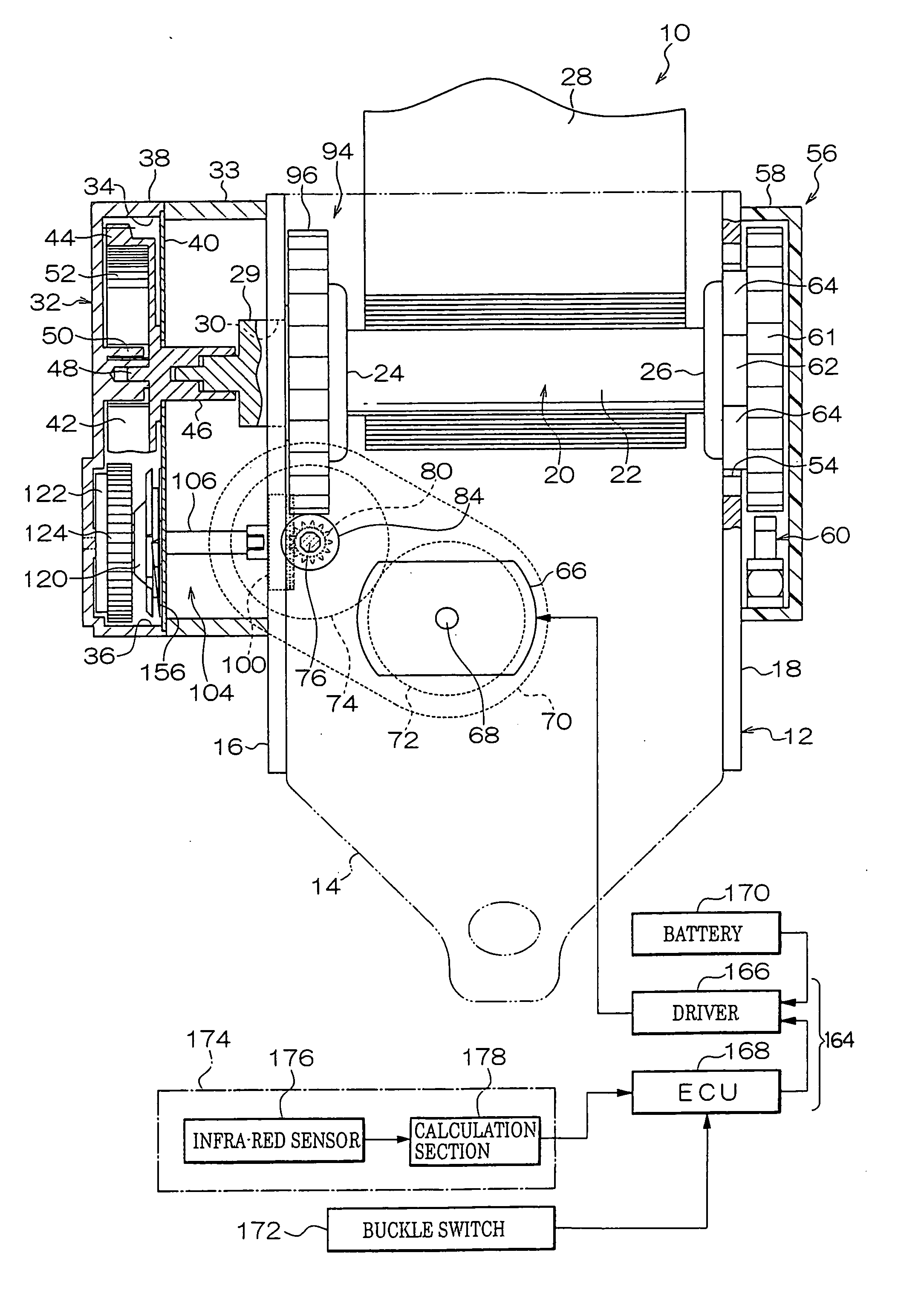
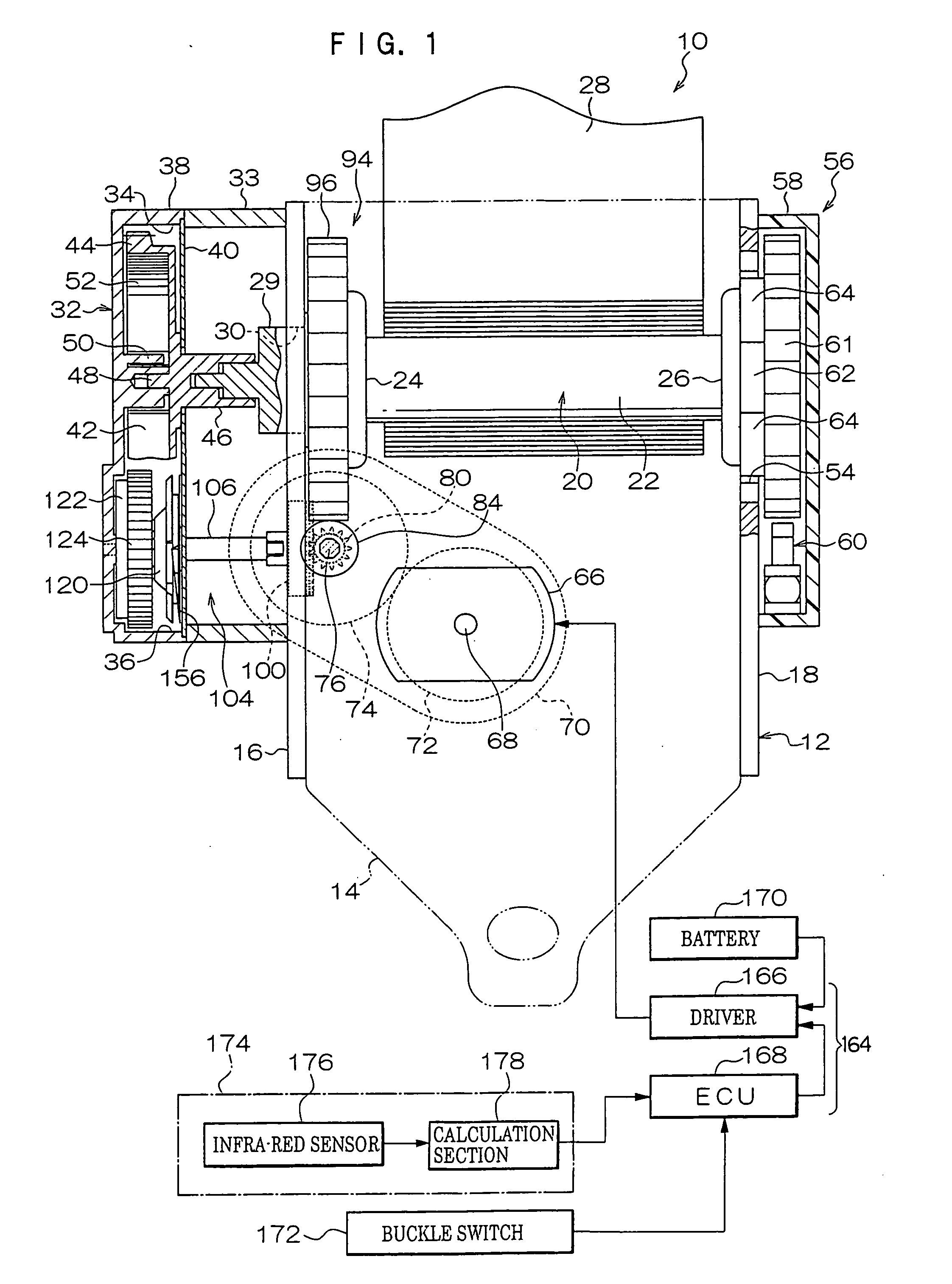
[0095]FIG. 1 shows a schematic rear sectional view of overall structure of a motorized retractor 10 relating to a first embodiment of the present invention.

[0096] As shown in FIG. 1, the motorized retractor 10 is provided with a frame 12. The frame 12 is provided with a substantially plate-form rear plate 14. This rear plate 14 is fixed to a vehicle body by an unillustrated fastening mechanism such as bolts or the like. Thus, the motorized retractor 10 is fixed to the vehicle body. A pair of leg pieces 16 and 18 are provided extending from both ends in the width direction of the rear plate 14, in parallel with one another. A spool 20, which is produced by die-casting or the like, is rotatably disposed between the leg pieces 16 and 18.

[0097] The spool 20 is provided with a spool main body 22 and a pair of flange portions 24 and 26, at two end portions of the spool main body 22. The spool main body 22 has a substantially tubular form, and the two flange portions 24 and 26 are each f...

second embodiment

[0183] Next, a second embodiment of the present invention will be described. Note that structures and operations that are essentially the same as in the first embodiment are assigned the same reference numerals as in the first embodiment, and descriptions thereof are omitted.

[0184]FIG. 12 shows a schematic exploded perspective view of principal elements of a motorized retractor 200 relating to the second embodiment of the present invention.

[0185] The motorized retractor 200 has a structure that is basically similar to the motorized retractor 10 relating to the first embodiment, but differs in the following respects.

[0186] As shown in FIG. 12, the motorized retractor 200 is provided with a case 202. The case 202 has a structure basically the same as the case 32 of the motorized retractor 10 relating to the first embodiment, and is provided with a case main body 204 and the cover 40 (see FIG. 13). The case main body 204 is provided with the first accommodation portion 34 and a seco...

third embodiment

[0220] Next, a third embodiment of the present invention will be described. Note that structures and operations that are essentially the same as in the first and second embodiments are assigned the same reference numerals as in the first and second embodiments, and descriptions thereof are omitted.

[0221]FIG. 20 shows a schematic plan sectional view of principal elements of a reverse driving force transmission mechanism which is a structural member of a motorized retractor 300 relating to the third embodiment of the present invention.

[0222] This motorized retractor 300 has a structure that is basically similar to the motorized retractor 200 relating to the second embodiment but, as shown in FIG. 20, a second clutch 302, which structures the reverse driving force transmission mechanism of the motorized retractor 300, is partially different from the second clutch 212 which structures the reverse driving force transmission mechanism of the motorized retractor 200.

[0223] The second cl...


PUM


Abstract

A motorized retractor which includes a spool with a webbing wound therearound, a reversible motor, a forward and a reverse driving force transmission mechanisms. The forward and the reverse driving force transmission mechanisms are provided between the spool and an output shaft of the motor, respectively. The forward driving force transmission mechanism reduces forward rotation of the output shaft by a predetermined reduction ratio and transmits this rotation to the spool for rotating the spool in a winding direction. The reverse driving force transmission mechanism reduces reverse direction rotation of the output shaft by a reduction ratio which is lower than the predetermined reduction ratio of the forward driving force transmission mechanism, and transmits this rotation to the spool for rotating the spool in the winding direction. The forward and the reverse driving force transmission mechanisms both block transmission to the output shaft of rotations generated at the spool side.

Description

CROSS-REFERENCE TO RELATED APPLICATION [0001] This application claims priority under 35 USC 119 from Japanese Patent Application Nos. 2004-117915 and 2004-256079, the disclosures of which are incorporated by reference herein. BACKGROUND OF THE INVENTION [0002] 1. Field of the Invention [0003] The present invention relates to a motorized retractor which is employed at a seat belt apparatus for restraining the body of an occupant sitting on a seat of a vehicle or the like with a webbing, and which enables winding and unwinding of the webbing. [0004] 2. Description of the Related Art [0005] A seatbelt apparatus which restrains an occupant sitting in a seat with a long belt-form webbing is attached to a vehicle such as a passenger car or the like. Among such seatbelt apparatuses, a “three-point”-type seat belt apparatus is equipped with a retractor (a webbing winding device) which stores the webbing in a wound state and retains the webbing to be unwindable. [0006] The retractor is provi...

Claims


Application Information

Patent Timeline
IPC IPC(8): B60R22/46B60R22/48B60R22/44B65H75/48
CPCB60R22/44B60R22/46B60R2022/4466B60R2022/4666
Inventor MORI, SHINJI
Owner KK TOKAI RIKA DENKI SEISAKUSHO
Why Eureka
Try Eureka