Spool valve controlled VCT locking pin release mechanism
a technology of vct locking pin and release mechanism, which is applied in the direction of valve drives, couplings, machines/engines, etc., can solve the problems of affecting the operation of the valv
- Summary
- Abstract
- Description
- Claims
- Application Information
AI Technical Summary
Benefits of technology
Problems solved by technology
Method used
Image
Examples
second embodiment
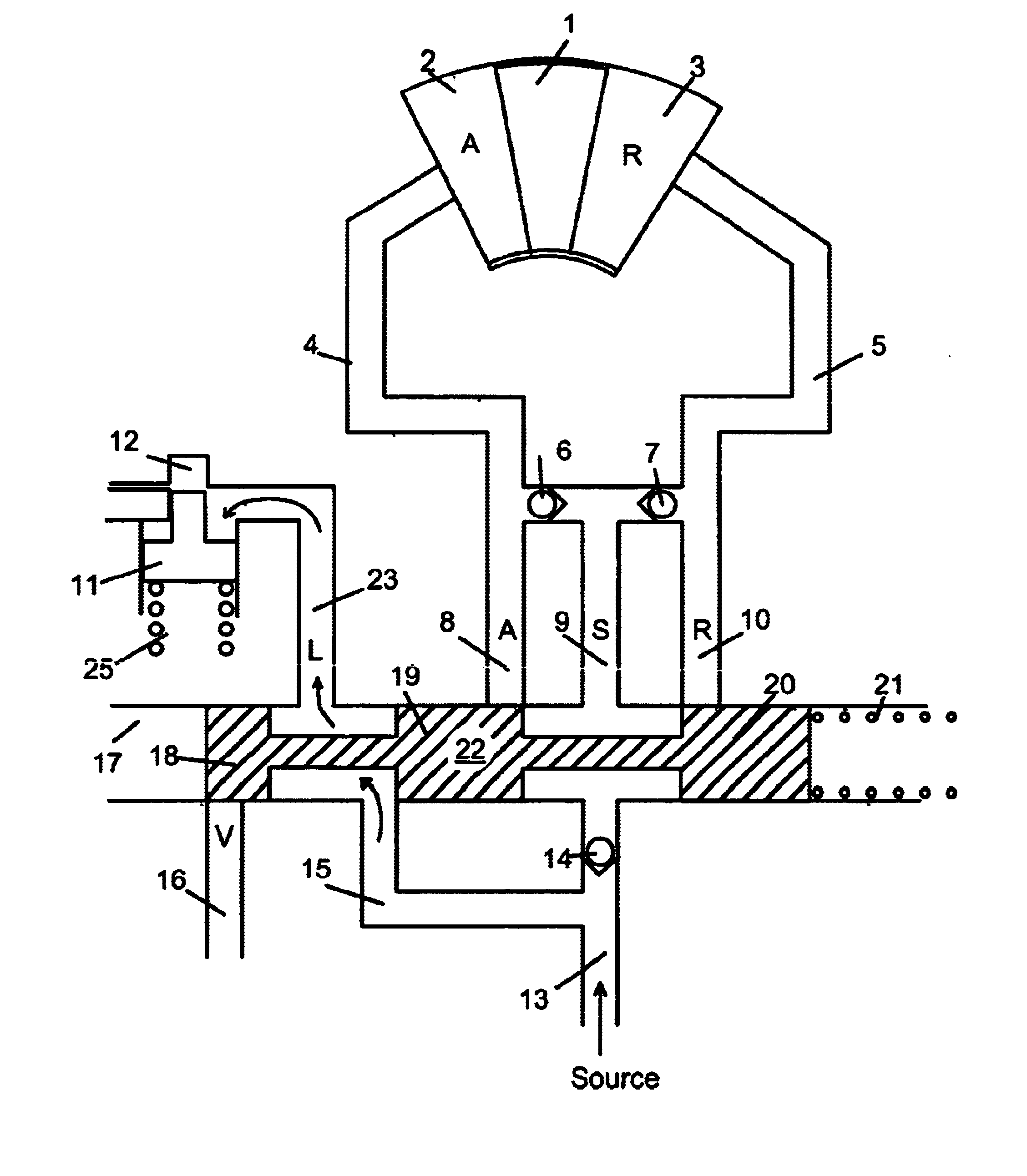
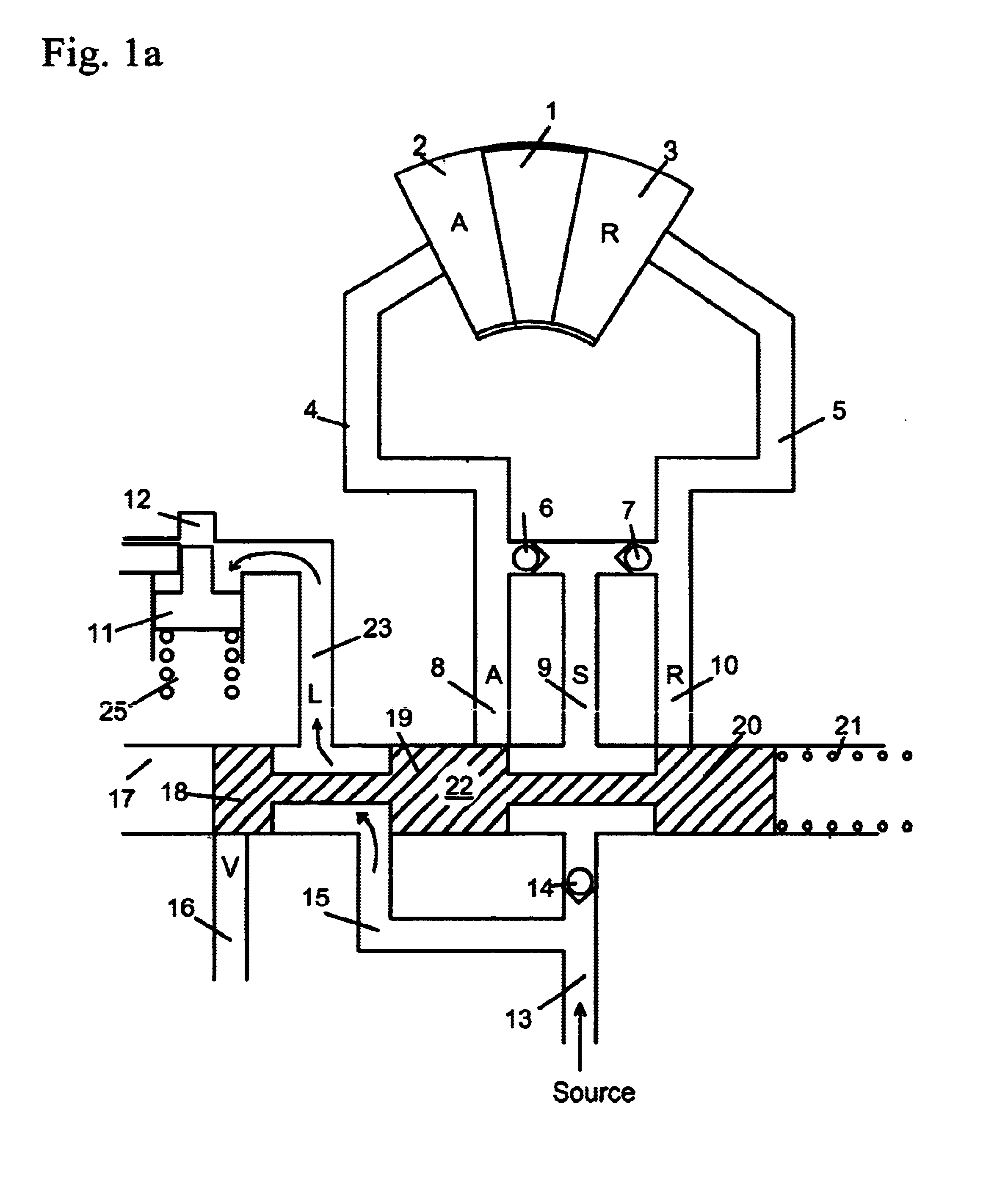
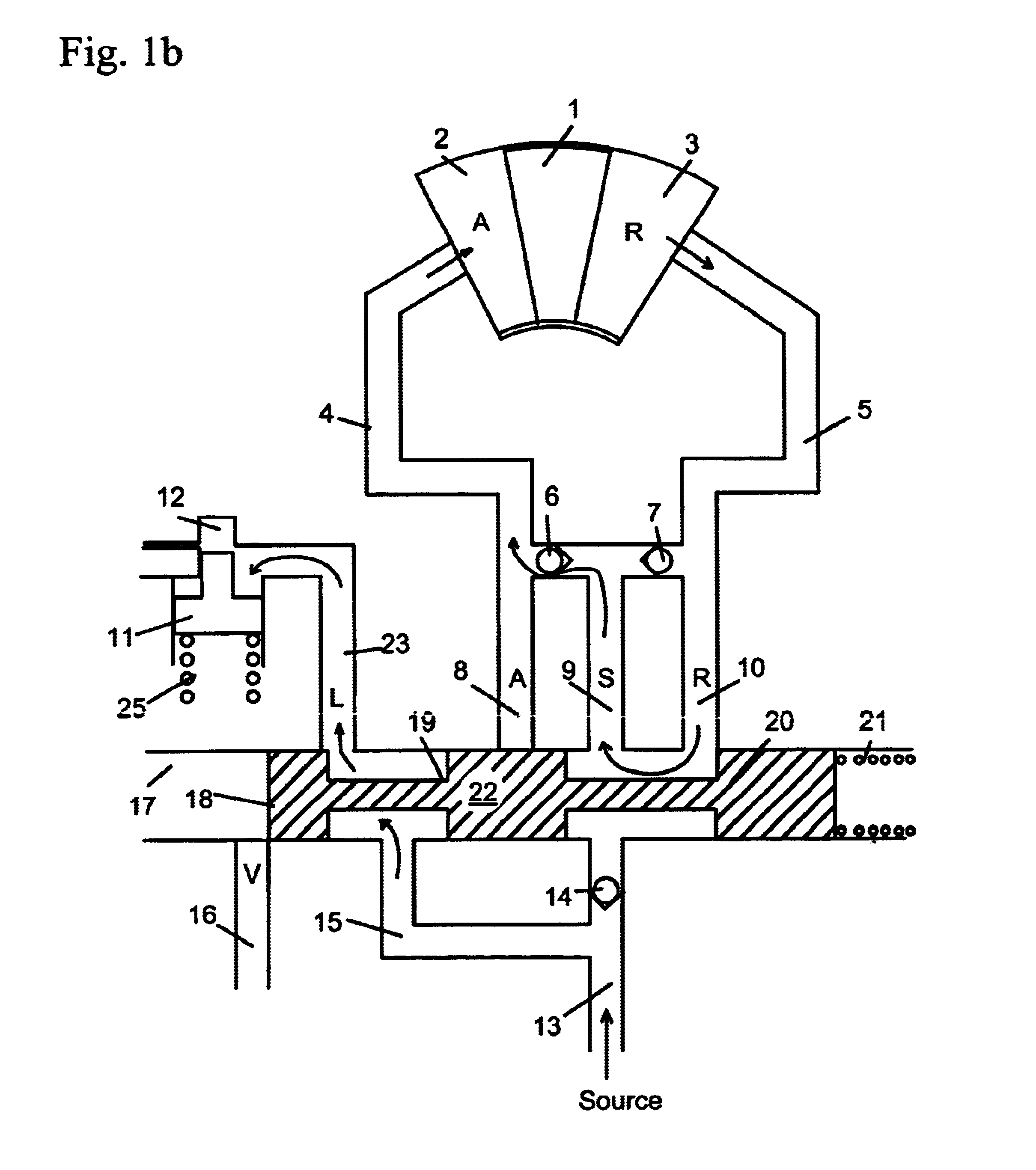
[0051]FIG. 5b shows the cam torque actuated phaser of the second embodiment in the retard position. For the retard position, the force of the biasing spring 125 is greater than the force of the VFS 120 (shown schematically) and the spool 109 is moved to the left in the drawing, causing the placement of spool land 109b to block retard port 115 and retard line 105. Spool land 109c blocks fluid from the second chamber 130 to lock port 138 and line 110 connected to the lock pin 111. Since fluid from spool passage 119b cannot reach line 110 or lock pin 111, the force of the biasing spring locks the lock pin 111 and fluid from the lock pin 111 exits through lock port 138 and line 110 to the third chamber 132, which is exhausted through vent port 122.
[0052]Hydraulic fluid enters the phaser from supply line 118 to common line 116. From common line 116, the fluid goes to the retard chamber 103 through check valve 107 and retard line 105. Fluid in the advance chamber 102, exits through advanc...
third embodiment
[0060]FIG. 7b shows the oil pressure actuated phaser of the third embodiment in the retard position. For the retard position, the force of the biasing spring 225 is greater than the force of the VFS 220 (shown schematically) and the spool 209 is moved to the left in the drawings, causing the placement of the spool land 209b to block advance port 214 and the advance line 204. Spool land 209c blocks fluid from the second chamber 230 to second advance port 244 leading to second advance line 240 and lock port 238 leading to line 110 and lock pin 211. Since fluid from spool passage 219b cannot reach line 210, the force of the biasing spring locks the lock pin 211. Fluid from the lock pin bore 212 exits through lock port 238 and line 210 to the third chamber 232. Fluid in the third chamber 232 is exhausted through vent 222.
[0061]Hydraulic fluid enters the phaser from supply line 218 to line 216 and port 226. From port 226, fluid enters the first chamber 228. Since spool land 209b blocks a...
fourth embodiment
[0070]FIG. 9b shows the single check valve torsion assist phaser of the fourth embodiment in the retard position. For the retard position, the force of the biasing spring 325 is greater than the force of the VFS 320 (shown schematically) and the spool 309 is moved to the left in the drawings, causing the placement of the spool land 309b to block advance port 314 and the advance line 304. Spool land 309c blocks fluid from the second chamber 330 to second advance port 344 leading to second advance line 340 and lock port 338 leading to line 310 and lock pin 311. Since fluid from spool passage 319b cannot reach line 310, the force of the biasing spring locks the lock pin 311. Fluid from the lock pin bore 312 exits through lock port 338 and line 310 to the third chamber 332. Fluid in the third chamber 332 is exhausted through vent 322.
[0071]Hydraulic fluid enters the phaser from supply line 318 containing a check valve 342 to line 316 and port 326. From port 326, fluid enters the first c...
PUM
 Abstract
Description
Claims
Application Information
 - R&D
- Intellectual Property
- Life Sciences
- Materials
- Tech Scout
- Unparalleled Data Quality
- Higher Quality Content
- 60% Fewer Hallucinations
Browse by: Latest US Patents, China's latest patents, Technical Efficacy Thesaurus, Application Domain, Technology Topic, Popular Technical Reports.
© 2025 PatSnap. All rights reserved.Legal|Privacy policy|Modern Slavery Act Transparency Statement|Sitemap|About US| Contact US: help@patsnap.com


