Flow control valve

a flow control and valve casing technology, applied in the direction of valve operating means/release devices, fuel injecting pumps, machines/engines, etc., can solve the problems of reducing durability, deteriorating lubricating performance, and inability to easily achieve the centering of the spool valve in the valve sliding space of the valve casing, etc., to achieve the effect of increasing durability, reliability, and responding

Inactive Publication Date: 2006-03-30
DENSO CORP
View PDF17 Cites 35 Cited by
  • Summary
  • Abstract
  • Description
  • Claims
  • Application Information

AI Technical Summary

Benefits of technology

[0013] The present invention is made in view of the above problems, and it is an object of the present

Problems solved by technology

In the electromagnetic type suction fuel amount adjusting valve disclosed in the above Japanese Patent publication, however, a centering of the spool valve in the valve sliding space of the valve casing can not be easily achieved due to a difference in a magnetic force, which is caused by a deviation of a clearance formed between an outer peripheral surface of a sliding portion of the spool valve and an inner surface of the valve sliding space of the valve casing.
Then, the outer peripheral surface of the sliding portion of the spool valve is pressed against the inner surface of the valve sliding space of the valve casing, and thereby a lubricating performance is deteriorated between the outer peripheral surface of the sliding portion of the spool valve and the inner surface of the valve sliding space of the valve casing.
As a result, the sliding portion of the spool valve may be stuck to the inner surface of the valve sliding space, and it may cause a problem of a decrease of durability.
In the above method, in which the spool valve is moved relative to the fluid port of the valve casing to adjust the fuel flow amount, since the spool valve is slowly moved to control the opening area of the fluid passage of the fluid port, a sliding speed of the spool valve with respect to the fluid port of the valve casing is extremely low, it would become difficult to form an oil film between the outer peripheral surface of the sliding portion of the spool valve and the inner surface of the valve sliding space of the valve casing.
The lubricating performance is thereby further deteriorated.
For example, an adjusting performance for fuel flow amount is deteriorated, as a result that response of the electromagnetic valve is deteriorated w

Method used


Image

  • Flow control valve
  • Flow control valve
  • Flow control valve

Examples


first embodiment

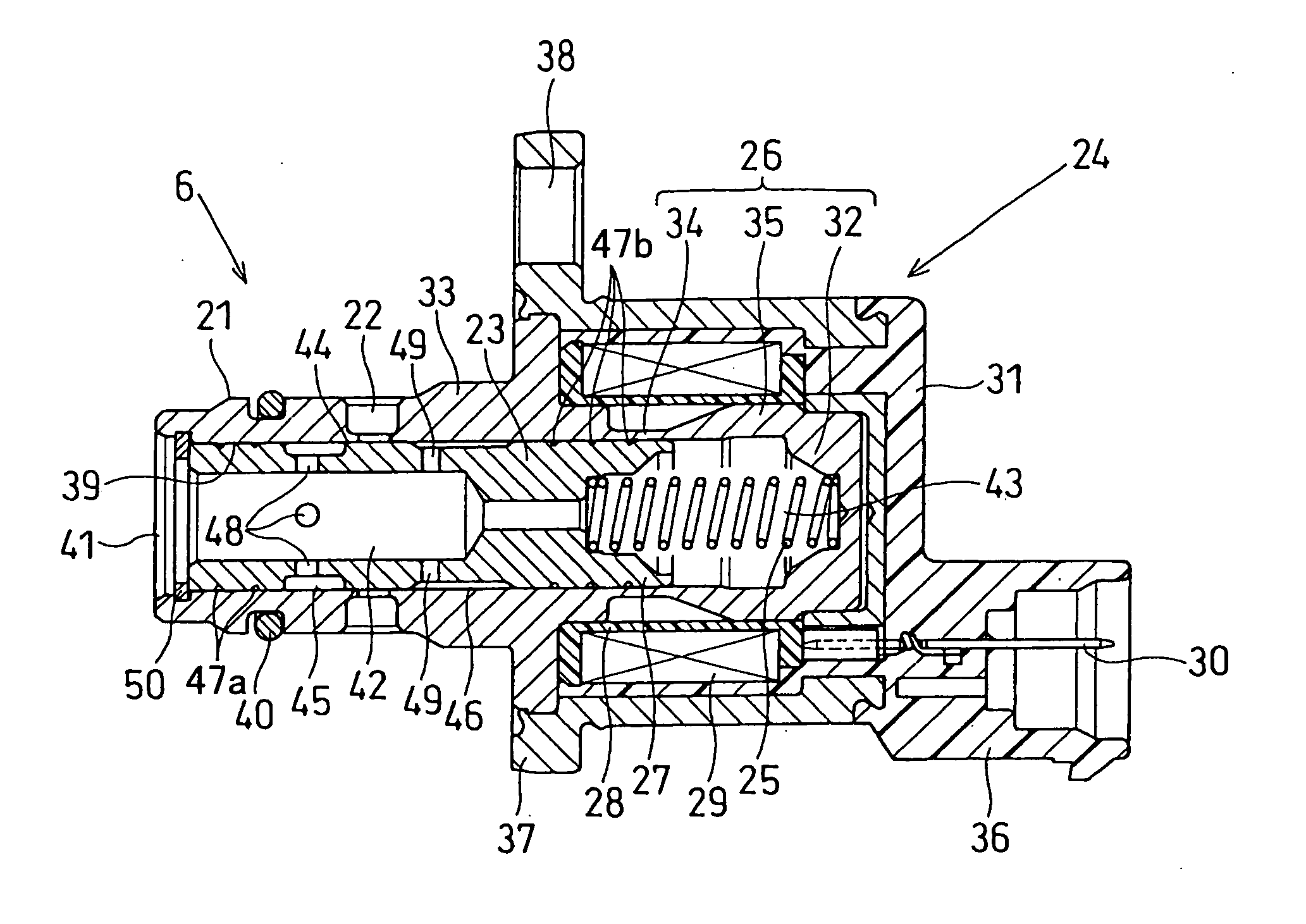
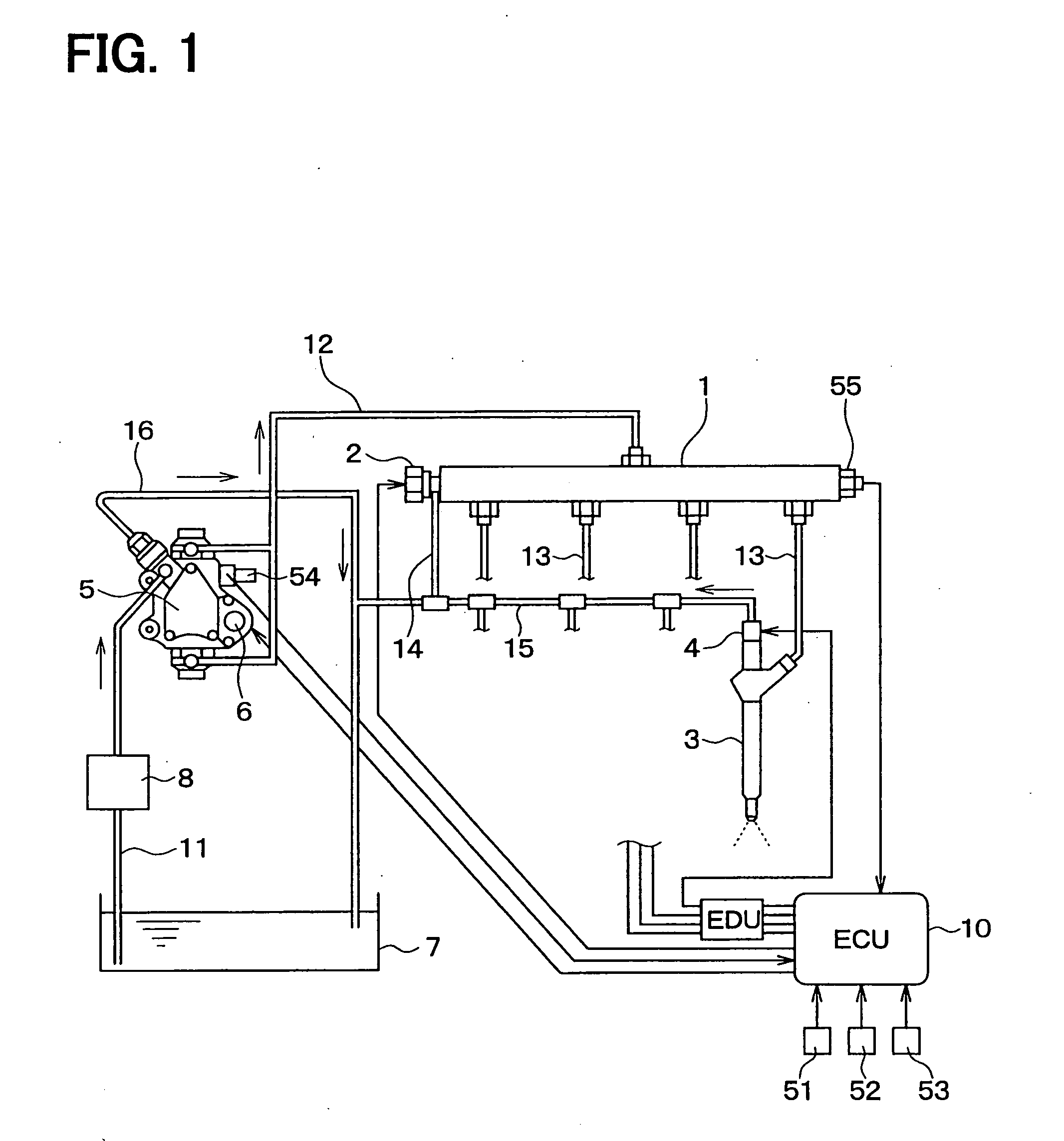
[0053] FIGS. 1 to 3 show a first embodiment of the present invention, wherein FIG. 1 is a view showing an entire structure of a common rail fuel injection system, FIG. 2 is a view showing an electromagnetic valve, and FIG. 3 is a view showing a spool valve of the electromagnetic valve for a supply pump.

[0054] A fuel injection apparatus for an internal combustion engine according to the embodiment is installed in a vehicle, such as an automotive vehicle. The fuel injection apparatus is, for example, a common rail fuel injection system (a fuel accumulated type injection apparatus) known as a fuel injection system for an internal combustion engine, such as a diesel engine (a multi cylinder diesel engine, hereinafter referred to as an engine). In the fuel injection apparatus, high pressure fuel accumulated in a common rail 1 is injected into combustion chambers of respective cylinders of the engine via multiple (four in this embodiment) electromagnetic fuel injection valves (injectors)...

second embodiment

[0081]FIG. 4 shows a second embodiment of the present invention, and is a view showing a spool valve 23 of the electromagnetic valve 6 of the supply pump.

[0082] According to the supply pump 5 of this embodiment, as in the same manner to the first embodiment, the circular flow amount adjusting groove 45, the circular centering groove 46 and multiple circular oil grooves 47a and 47b are formed at the sliding portion 44 of the spool valve 23 for controlling the suction amount of the fuel with sliding movement of the spool valve in the spool space 39 of the valve casing 21 of the electromagnetic valve 6. According to the embodiment, the first communication port 48 for communicating the inner flow passage (the through-hole) 42 with the flow amount adjusting groove 45 is formed, whereas the second communication port 49 for communicating the inner flow passage (the through-hole) 42 with the centering groove 46 is not formed. Instead of the second communication port 49, multiple communicat...

third embodiment

[0084]FIGS. 5A and 5B show a third embodiment of the present invention, and views showing a spool valve 23 of the electromagnetic valve of the supply pump.

[0085] According to the embodiment, communication ports 64, which communicate two centering grooves 46 respectively formed between the first and second sliding surface portions 23a and 23b of the sliding portion 44 with the inner flow passage (the through-hole) 42, are formed in the spool valve 23 to penetrate the sleeve portion thereof from its inner surface to its outer surface and formed at such positions eccentric to a perpendicular line of a center line for the spool valve 23. Namely, a center line of the respective second communication ports 64 is displaced from a radial line extending in a radial direction of the spool valve 23, when viewed on a plane perpendicular to the axial line of the spool valve 23.

[0086] With such an arrangement, the spool valve 23 will be rotated in the spool space 39 with respect to its center li...


PUM


Abstract

A spool valve is movably provided in a valve sliding space of a valve casing. The spool valve has a through-hole formed in the inside thereof, and a communication port formed in the spool valve is operatively communicated with a fluid port for controlling an opening area of the fluid port by moving within the valve sliding space. Multiple circular oil grooves are formed at an outer peripheral surface of the spool valve, into which high pressure fluid is supplied so that the spool valve can be smoothly moved in the valve sliding space.

Description

CROSS REFERENCE TO RELATED APPLICATION [0001] This application is based on Japanese Patent Application Nos. 2004-276313 filed on Sep. 24, 2004, 2005-159255 filed on May 30, 2005 and 2005-241964 filed on Aug. 24, 2005, the disclosures of which are incorporated herein by reference. FIELD OF THE INVENTION [0002] The present invention relates to a flow control valve having a spool valve movably held in a valve sliding space of a valve casing for adjusting an opening area of a fluid passage of a fluid port in order to control flow amount of fluid, such as fuel, oil, or air and so on. More particularly, the present invention relates to a suction fuel amount adjusting valve, which is assembled in a fuel supply pump for a common rail fuel injection system, and which adjusts fuel amount flowing from a feed pump into a pressurizing chamber of the fuel supply pump. BACKGROUND OF THE INVENTION [0003] In a common rail fuel injection system conventionally known as a fuel injection system for a di...

Claims


Application Information

Patent Timeline
IPC IPC(8): F16K31/02
CPCF02M59/34F02M59/366F02M63/0017F16K31/0668F02M63/0225F16K3/262F16K31/0648F02M63/004
Inventor MORI, KATSUMIFUJII, HIROTOAKASHI, NOBUHIRO
Owner DENSO CORP
Why Eureka
Try Eureka