Spool valve manifold interconnect for a filter system

a filter system and manifold technology, applied in the direction of filtration separation, multi-stage water/sewage treatment, separation process, etc., can solve the problems of valves becoming difficult to operate, fluid flow from the system must be shut off, and the filtration system may not always be placed in the most accessible location

Active Publication Date: 2012-01-17
3M INNOVATIVE PROPERTIES CO
View PDF32 Cites 35 Cited by
  • Summary
  • Abstract
  • Description
  • Claims
  • Application Information

AI Technical Summary

Benefits of technology

[0016]In even another aspect, the spool valve manifold further may include a first seal located between the valve body and the valve housing and configured to prevent fluid leakage from the first fluid flow path and a second seal located between the valve body and the valve housing and configured to prevent fluid leakage from the second fluid flow path.
[0017]In another aspect, the spool valve manifold may also include a third seal located between the valve body and the valve housing and configured to prevent fluid leakage from the third fluid flow path.

Problems solved by technology

Unfortunately, such fluid filtration system may not always be placed in the most accessible location or at the most desirable orientation for a user to remove the old fluid filter cartridge and install a new one.
Further compounding the problem of removing the old fluid filter cartridge from the fluid supply system is that the flow of fluid from the system must be shut off prior to removal of the replacement fluid filter cartridge.
One disadvantage of the prior art is that the valves can become hard to operate due to the sealing O-rings taking a compression set over time.
Because of this compression set, a high breaking force to initially move the valve is required.

Method used


Image

  • Spool valve manifold interconnect for a filter system
  • Spool valve manifold interconnect for a filter system
  • Spool valve manifold interconnect for a filter system

Examples


Embodiment Construction

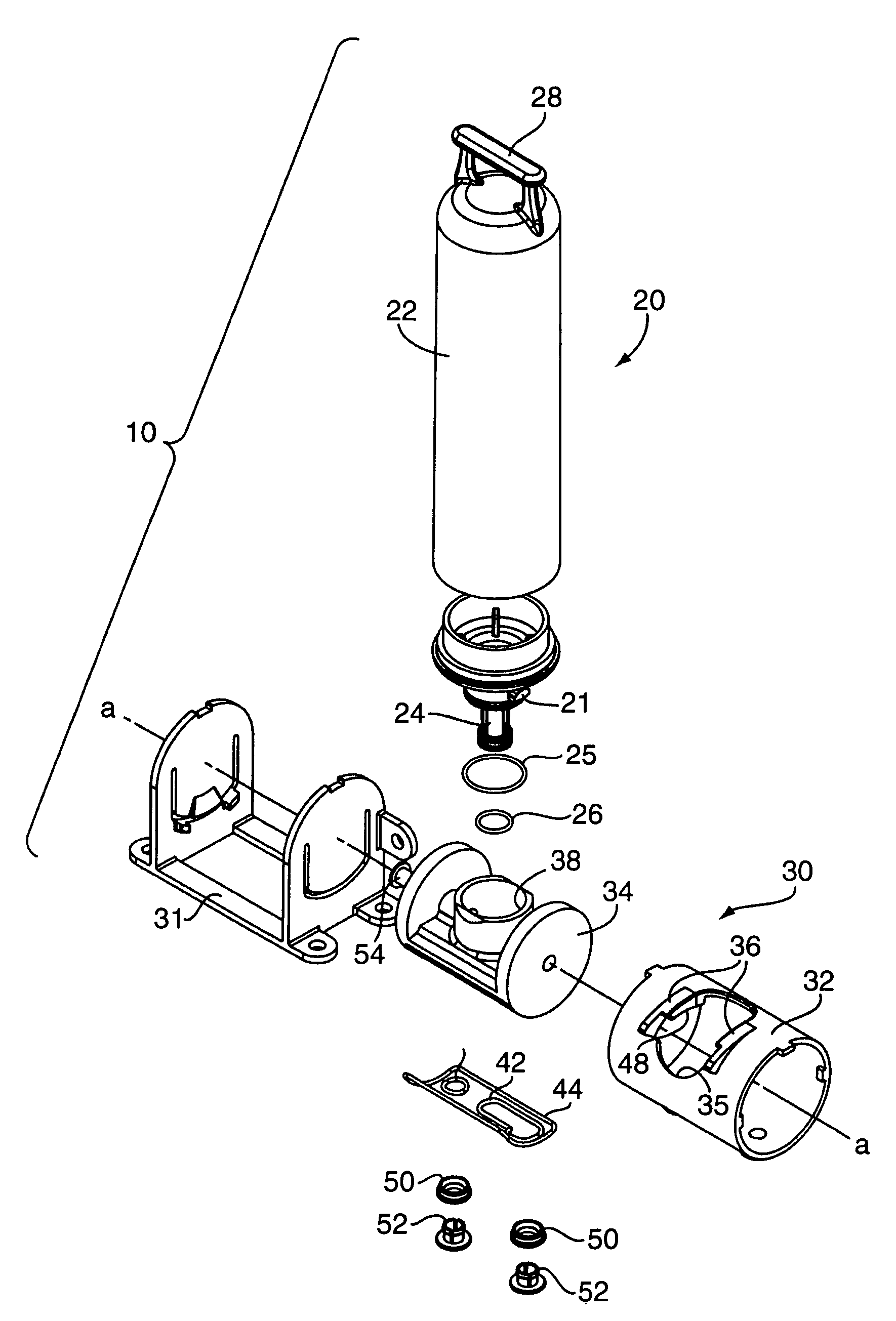
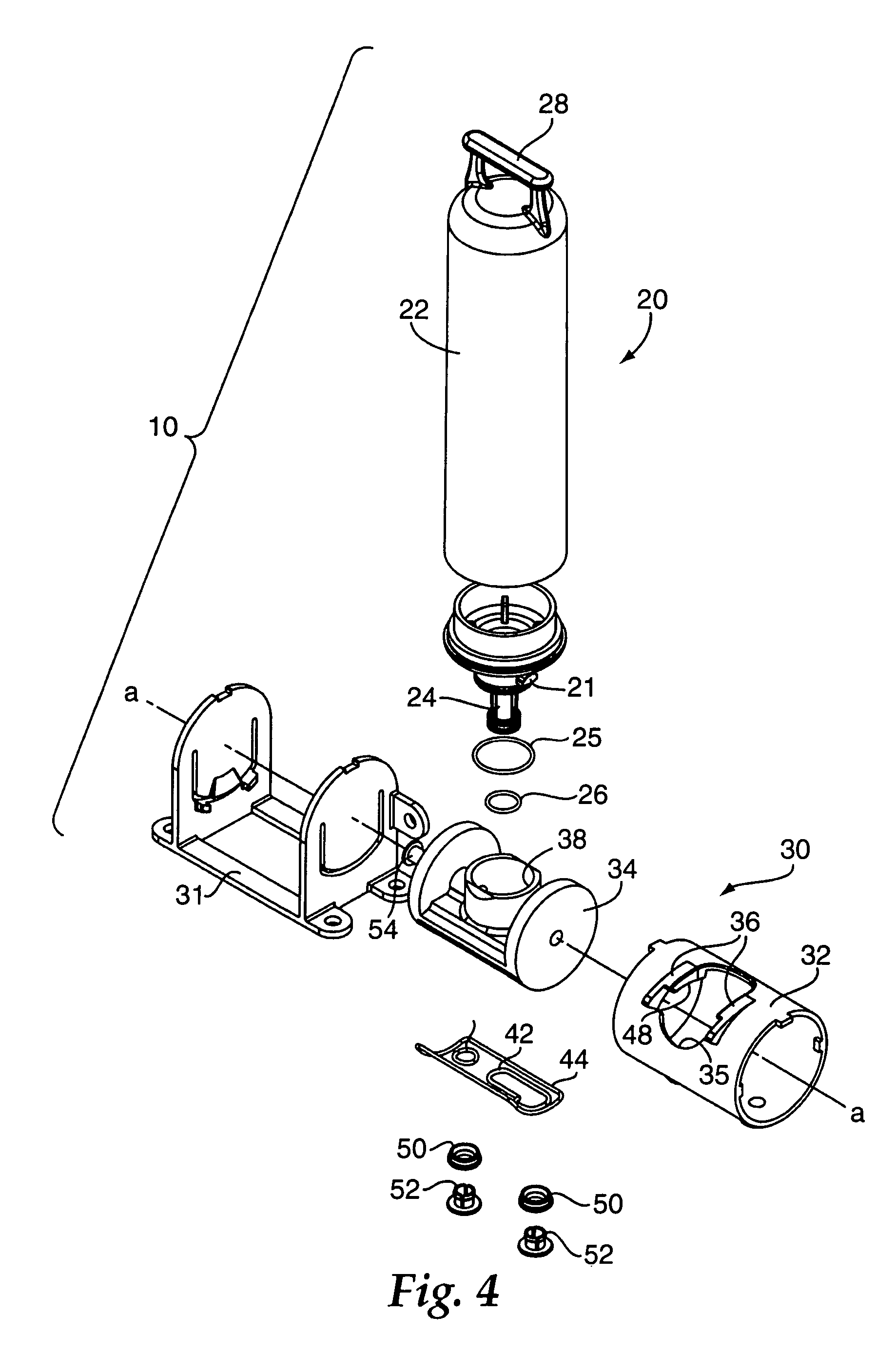
[0050]As discussed hereinabove, the present disclosure overcomes several disadvantages associated with the prior art fluid filter systems. The advantages and other features of the fluid filter systems, comprising a representative manifold assembly and a representative replaceable fluid filter cartridge containing filter media, disclosed herein, will become more readily apparent to those having ordinary skill in the art from the following detailed description of the representative embodiments taken in conjunction with the drawings which set forth some representative embodiments of the present disclosure.

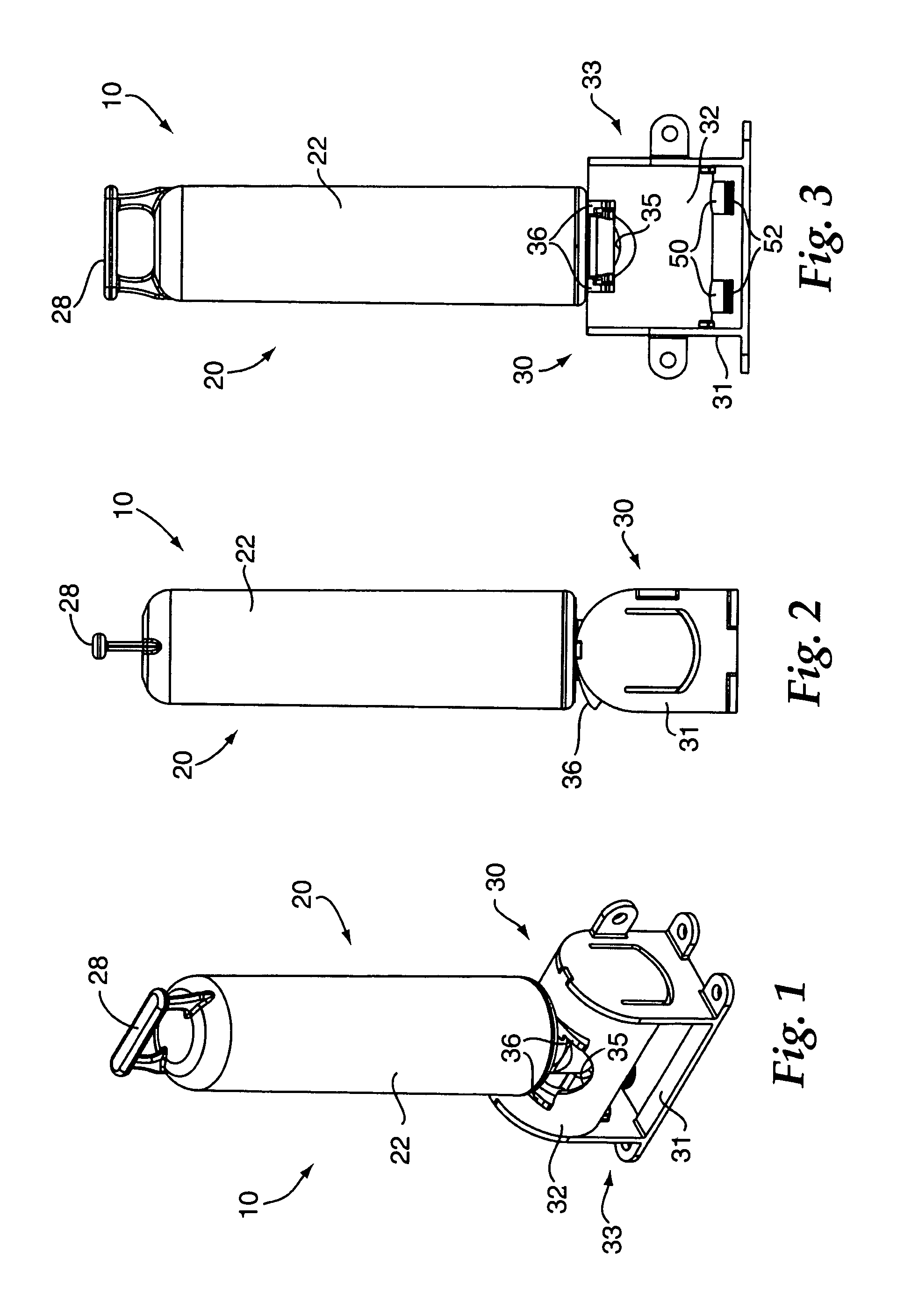
[0051]Referring now to the drawings wherein like reference numerals identify similar structural elements and / or features of the subject disclosure, there is illustrated in FIGS. 1-3 a representative fluid filter cartridge and a representative spool valve manifold assembly constructed in accordance with an exemplary, representative embodiment of the subject disclosure and designated ge...


PUM

PropertyMeasurementUnit
angleaaaaaaaaaa
angleaaaaaaaaaa
pressureaaaaaaaaaa

Abstract

A filter cartridge and spool valve manifold assembly includes a filter cartridge and a spool valve manifold. The filter cartridge includes a filter element and inlet / outlet portion in fluid communication with the filter element. The inlet / outlet portion has a cartridge inlet port and a cartridge outlet port. The spool valve manifold includes a housing and a body. The housing has a housing inlet port and a housing outlet port adapted for fluid communication with a fluid supply system. The body is located within the housing and configured to rotate around a first axis relative to the housing. The inlet / outlet portion of the filter cartridge is fluidly coupled to the body via insertion of the inlet / outlet portion into the body in a direction perpendicular to the first axis.

Description

RELATED APPLICATIONS[0001]This application is a continuation-in-part of commonly owned U.S. Provisional Patent Application Ser. No. 60 / 681,649, filed May 16, 2005, of Tubby, entitled “SPOOL VALVE INTERCONNECT FOR A FILTER SYSTEM,” the disclosure of each is herein incorporated by reference to the extent not inconsistent with the present disclosure.BACKGROUND OF THE DISCLOSURE[0002]The present disclosure relates in general to a system operatively positioned in a fluid supply system comprising a manifold assembly and a replaceable fluid filter cartridge containing filter media, the manifold assembly having the capability for facilitating the removal of a first replaceable fluid filter cartridge and then having the capability for facilitating the installation of another replaceable fluid filter cartridge therein in a fluid supply system and, in particular, to a spool valve manifold assembly that facilitates the quick and easy removal and installation of the replaceable fluid filter cart...

Claims


Application Information

Patent Timeline
Patent Type & Authority Patents(United States)
IPC IPC(8): B01D35/153
CPCB01D27/08B01D35/153C02F9/005F16K5/0414B01D27/108B01D27/106B01D2201/4023B01D2201/4046Y10T29/49826B01D2201/4061B01D2201/4053Y10T137/86863C02F9/20C02F9/00
Inventor TUBBY, BRIAN J.BASSETT, LAURENCE W.
Owner 3M INNOVATIVE PROPERTIES CO
Why Eureka
Try Eureka