Automatic inspection device for wire rods

A technology of automatic inspection and take-up device, applied in the direction of optical testing flaws/defects, etc., can solve the problems of low inspection efficiency, inability to guarantee product quality, defective or defective products are not detected, etc., to achieve simple operation, compact structure, Easy to install effect

Inactive Publication Date: 2012-12-26
杭州良淋电子科技股份有限公司
View PDF13 Cites 10 Cited by
  • Summary
  • Abstract
  • Description
  • Claims
  • Application Information

AI Technical Summary

Problems solved by technology

Regardless of the inspection method of the above two methods, not only the inspection efficiency is low, but also there will ine

Method used


Image

  • Automatic inspection device for wire rods
  • Automatic inspection device for wire rods
  • Automatic inspection device for wire rods

Examples


Embodiment 1

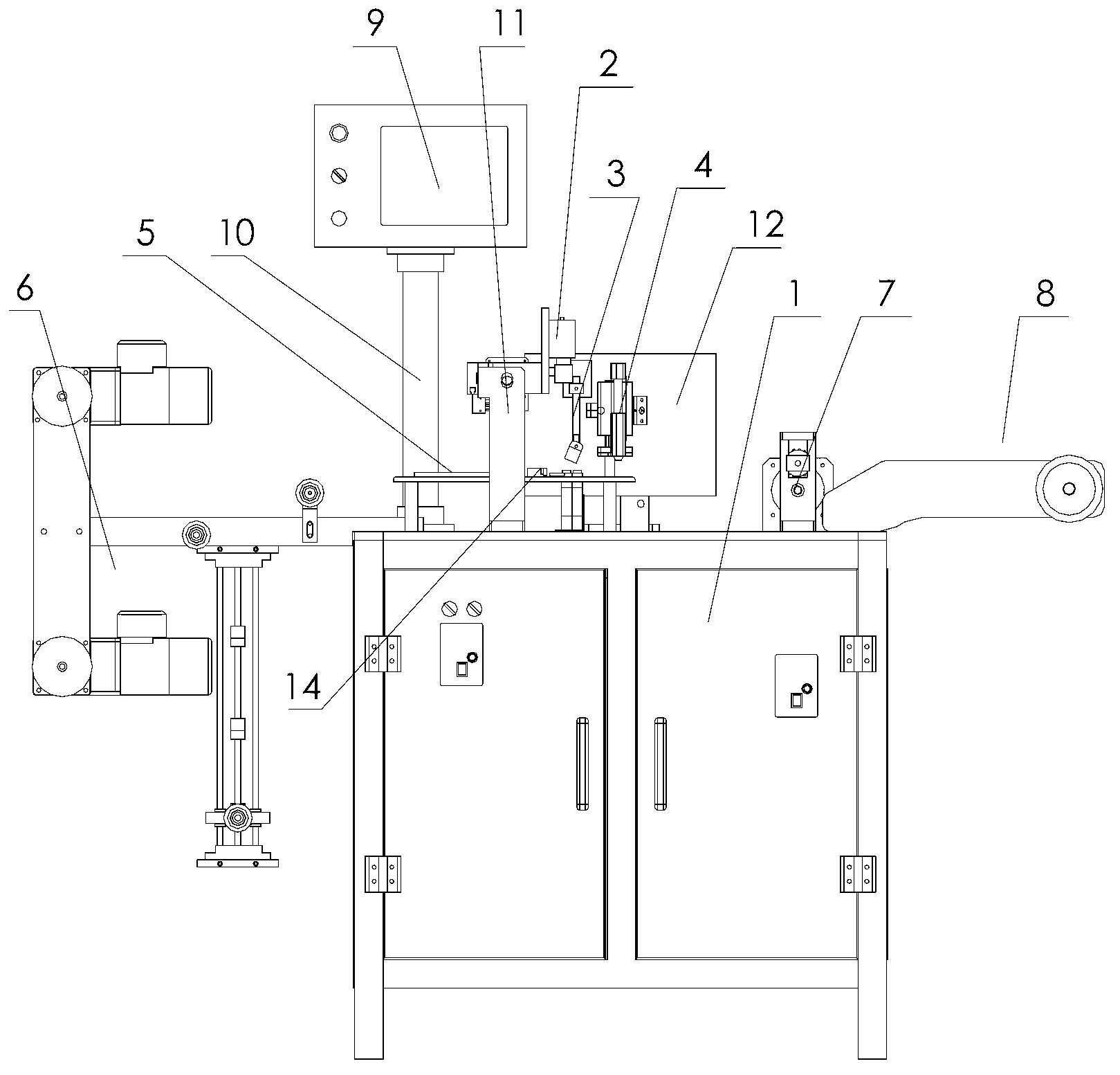
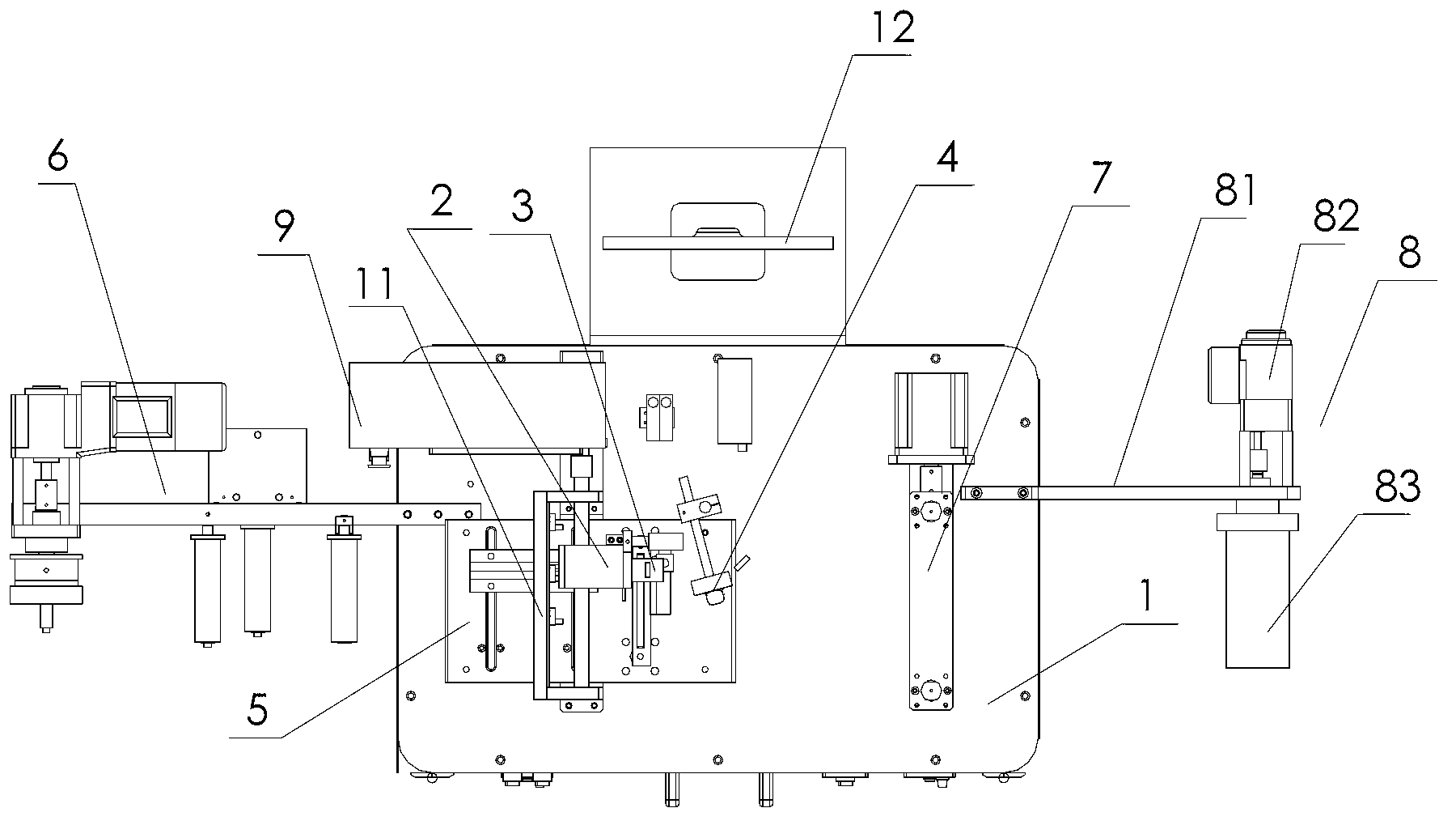
[0023] Embodiment 1: refer to Figure 1~9 . An automatic wire inspection device, comprising a control cabinet 1, a CCD visual inspection module 2, an LED light source 3, a marking module 4, a wire fixing plate 5, an automatic wire pay-off device 6, a traction device 7, a wire take-up device 8 and an operation panel 9 , the left side of the upper end of the control cabinet 1 is provided with an automatic wire pay-off device 6, and the right side of its upper end is provided with a wire take-up device 8 driven by a wire take-up motor 82, and the wire fixing plate 5 is set on the upper end of the control cabinet 1, and the wire fixing plate 5 From left to right, there are CCD visual inspection module 2, LED light source 3, and marking module 4 in order at the top. The operation panel 9 is set above the control cabinet 1 through the column 10. The control cabinet 1 between the wire fixing plate 5 and the wire take-up device 8 The top is provided with traction device 7.

[0024] ...


PUM


Abstract

The invention relates to an automatic inspection device for wire rods. The automatic inspection device comprises a control cabinet, a charge coupled device (CCD) vision inspection module, a light emitting diode (LED) light source, a marking module, a wire rod fixing plate, an automatic wire rod unwinding device, a dragging device, a winding device and an operating panel, wherein the automatic wire rod unwinding device is arranged on the left side of the upper end of the control cabinet; the winding device driven by a winding motor is arranged on the right side of the upper end; the wire rod fixing plate is arranged at the upper end of the control cabinet; the CCD vision inspection module, the LED light source and the marking module are sequentially arranged above the wire rod fixing plate from left to right; the operating panel is arranged above the control cabinet through a vertical column; and the dragging device is arranged above the control cabinet between the wire rod fixing plate and the winding device.

Description

technical field [0001] The invention relates to an electronic wire inspection device, in particular to an automatic wire inspection device. Background technique [0002] Electronic wire, English is: ELECTRIC WIRE, generally used for weak current projects, such as internal wiring of electronic and electrical equipment, etc., its structure can basically be shaped into a number of bare copper wires or tinned copper wires or other wires packaged side by side in the outer insulation layer. Due to its specific form of wire distribution, during production, the wires will cross each other or have a cross-short circuit. After the package is formed, it can be identified as a substandard product, and electronic wires are often produced in rolls. The inspection is often done manually. According to the current inspection methods, the inspection of electronic wires is mainly through manual sampling inspection, or placed on an automatic conduction device, and the coiled electronic wires a...

Claims


Application Information

Patent Timeline
IPC IPC(8): G01N21/89
Inventor 杨平汤红富李磊
Owner 杭州良淋电子科技股份有限公司
Why Eureka
Try Eureka