
Port pin test fixture

A technology of testing fixtures and pins, which is applied in the direction of the measuring device casing, etc., can solve the problems of reducing test efficiency, easily scratching products, and small storage space, so as to prevent fixtures from scratching products, improve testing efficiency, and save maintenance costs. with space effect

Inactive Publication Date: 2015-08-26
KUSN MAIZHI FIXTURE TECH
View PDF6 Cites 0 Cited by
  • Summary
  • Abstract
  • Description
  • Claims
  • Application Information

AI Technical Summary

Problems solved by technology

[0002] When testing the regular plug-in ports of electronic products, two cylinders are usually used, one for pushing the probe and the other for pressing the product. The disadvantages of this design are as follows: direct cost increases and the volume is large; some products need to be placed in the test In the shielding box, the volume of the shielding box is too large, which is not easy to operate; it is easy to scratch the product, and the storage space is small; the operator needs to avoid it carefully during the test, which greatly reduces the test efficiency

Method used


Image

  • Port pin test fixture

Examples


Embodiment Construction

[0012] In order to make the technical solutions, technical features, goals and effects achieved by the present invention easy to understand, the present invention will be further described below in conjunction with specific embodiments.

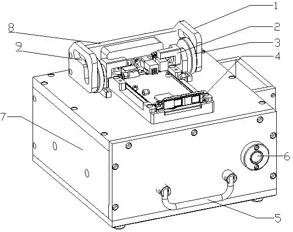
[0013] according to figure 1 , port pin test fixture, it is characterized in that: comprise base box 7, be placed on the movable needle plate 8 on the base box 7, be fixed on the guide rail plate 1 of needle plate 8, the track groove that rotation is fixed on guide rail plate 1 The turntable 3 of 9, the pressing block 2 connected with the turntable 3, and the product positioning module 4 arranged on the bottom box 7. The needle plate 8 is connected with the cylinder, and the cylinder is located in the bottom case 7 . The end of the bottom box 7 is provided with a handle 5 for moving the bottom box 7 and a switch 6 for controlling the opening and closing of the whole jig. The needle plate 8 and the rail plate 1 are located on the linear slid...


PUM


Abstract

The invention belongs to the field of finished electronic product test jigs, and particularly relates to a port pin test jig, in particular to a test jig for frequently plugged ports of electronic products. The port pin test jig is characterized in that: the port pin test jig comprises a base case, a movable pin plate, guide way plates, turnplates, holddowns and a product-positioning module, the pin plate is placed on the base case, the guide way plates are fixed on the pin plate, the turnplates are rotatably fixed in guide ways of the guide way plates, the holddowns are connected with the turnplates, and the product-positioning module is arranged on the base case. The port pin test jig uses an air cylinder to move the pin plate and the guide way plates together, and achieves the double functions of pressing a product and pushing the pin plate to move, the product to be tested can be effectively fixed, the cost is saved, the jig space is saved, and operation is convenient; after the pin plate backs off, the holddowns can rotate, and are completely separated from the product in the vertical view, the product can be prevented from being scraped by the jig when being placed, the speed of placing the product is increased, and the test efficiency is increased.

Description

technical field [0001] The invention belongs to the field of testing jigs for electronic finished products, and in particular relates to a testing jig for port insertion pins, in particular to a testing jig for frequently plugged ports of electronic products. Background technique [0002] When testing the regular plug-in ports of electronic products, two cylinders are usually used, one for pushing the probe and the other for pressing the product. The disadvantages of this design are as follows: direct cost increases and the volume is large; some products need to be placed in the test In the shielding box, the volume of the shielding box is too large, which is not easy to operate; it is easy to scratch the product, and the storage space is small; the operator needs to avoid it carefully during the test, which greatly reduces the test efficiency. The port insertion pin test fixture of the present invention overcomes the above defects, reduces the production cost and increases ...

Claims


Application Information

Patent Timeline
Patent Type & Authority Patents(China)
IPC IPC(8): G01R1/04
Inventor 蔡青春
Owner KUSN MAIZHI FIXTURE TECH
Learn More