Waveform display method for virtual oscillograph

A waveform display and oscilloscope technology, applied in the field of virtual oscilloscopes, can solve the problems of indeterminate visual effects of motion, static periodic signals, sometimes moving to the left, sometimes moving to the right or sometimes reversed waveforms, and interface confusion, so as to achieve optimized display. The way, the method is simple, the visual effect is comfortable

Inactive Publication Date: 2014-07-09
SOUTHEAST UNIV
View PDF4 Cites 0 Cited by
  • Summary
  • Abstract
  • Description
  • Claims
  • Application Information

AI Technical Summary

Problems solved by technology

[0003] When using fixed-point redrawing waveforms, due to the different selection of redrawing points, visually the same periodic signal may sometimes be static, sometimes move to the left, sometimes move to the right, or sometimes the waveform is reversed, although in fact these waveforms are always in the Move to the left; for multiple periodic signals with different frequencies, when they are displayed on the same coordinate axis at the same time, the visual effect of the above-mentioned waveform movement direction will also appear, and the interface will be confusing

Method used


Image

  • Waveform display method for virtual oscillograph
  • Waveform display method for virtual oscillograph
  • Waveform display method for virtual oscillograph

Examples


Embodiment Construction

[0026] The present invention will be further described below in conjunction with the accompanying drawings and specific embodiments, but not as a limitation of the present invention.

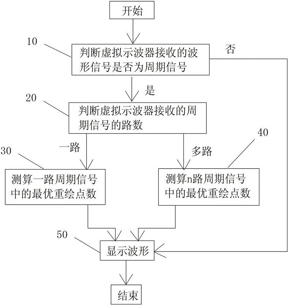
[0027] Such as figure 1 Shown, a kind of waveform display method for virtual oscilloscope of the present invention comprises the following steps:

[0028] 10) Determine whether the waveform signal received by the virtual oscilloscope is a periodic signal. If it is a periodic signal, go to step 20). If it is not a periodic signal, the virtual oscilloscope directly displays the received signal.

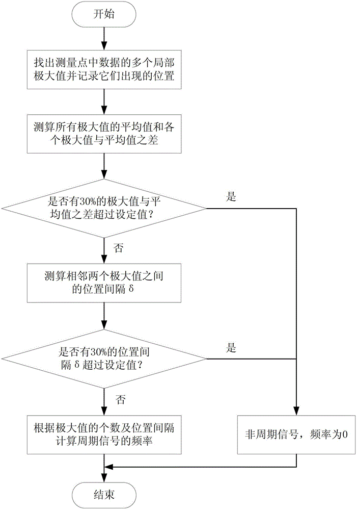
[0029] In step 10), there are many methods for judging whether the signal received by the virtual oscilloscope is a periodic signal, such as zero-crossing method, sampling signal spectrum analysis and power spectrum estimation. In the present invention, the following method is preferred for judging whether the signal received by the virtual oscilloscope is a periodic signal. Such as figure 2 As shown,...


PUM


Abstract

The invention discloses a waveform display method for a virtual oscillograph. The waveform display method comprises the following steps: (10) judging whether waveform signals received by the virtual oscillograph are periodic signals, if so, entering step (20), and if not, directly displaying the received signals; (20) judging way of the periodic signals received by the virtual oscillograph, entering step (30) if the periodic signals are determined to be one-way periodic signals and entering step (40) if the periodic signals are determined to be n-way periodic signals; (30) measuring and calculating optimal repainting point number in the one-way periodic signals; (40) measuring and calculating optimal repainting point number in the n-way periodic signals; and (50) displaying a waveform. According to the waveform display method, the one-way periodic signals can move along a specified direction, or the n-way periodic signals can move along a specific direction in maximum quantity, so that the visual effect of the virtual oscillograph can be improved.

Description

technical field [0001] The invention relates to the field of virtual oscilloscopes, in particular to a waveform display method for virtual oscilloscopes. Background technique [0002] Virtual oscilloscope is one of the development hotspots of today's instrument technology. Many industrial equipment need to display and save working condition waveforms, such as wind power converters. For the virtual oscilloscope software with real-time monitoring function, the real-time and stability requirements of its data acquisition and waveform display are higher. If timing redrawing is used, high-precision timing will lead to a higher processor occupancy rate. In addition, the clock asynchrony between the computer and the external acquisition device will also cause the amount of data received by the virtual oscilloscope software within a fixed time to be inconsistent. , resulting in shaking of the displayed waveform. In order to display the periodic waveform smoothly, the method of fix...

Claims


Application Information

Patent Timeline
Patent Type & Authority Patents(China)
IPC IPC(8): G01R13/00
Inventor 叶桦孟玉静孙晓洁仰燕兰
Owner SOUTHEAST UNIV
Why Eureka
Try Eureka