Fault detection and reduction in logic circuit

A logic circuit, fault technology, applied in the field of designing high-integrity logic circuits

Active Publication Date: 2012-12-26
WESTINGHOUSE ELECTRIC CORP
View PDF8 Cites 18 Cited by
  • Summary
  • Abstract
  • Description
  • Claims
  • Application Information

AI Technical Summary

Problems solved by technology

Any mismatch will result in a prede

Method used


Image

  • Fault detection and reduction in logic circuit
  • Fault detection and reduction in logic circuit
  • Fault detection and reduction in logic circuit

Examples


Embodiment Construction

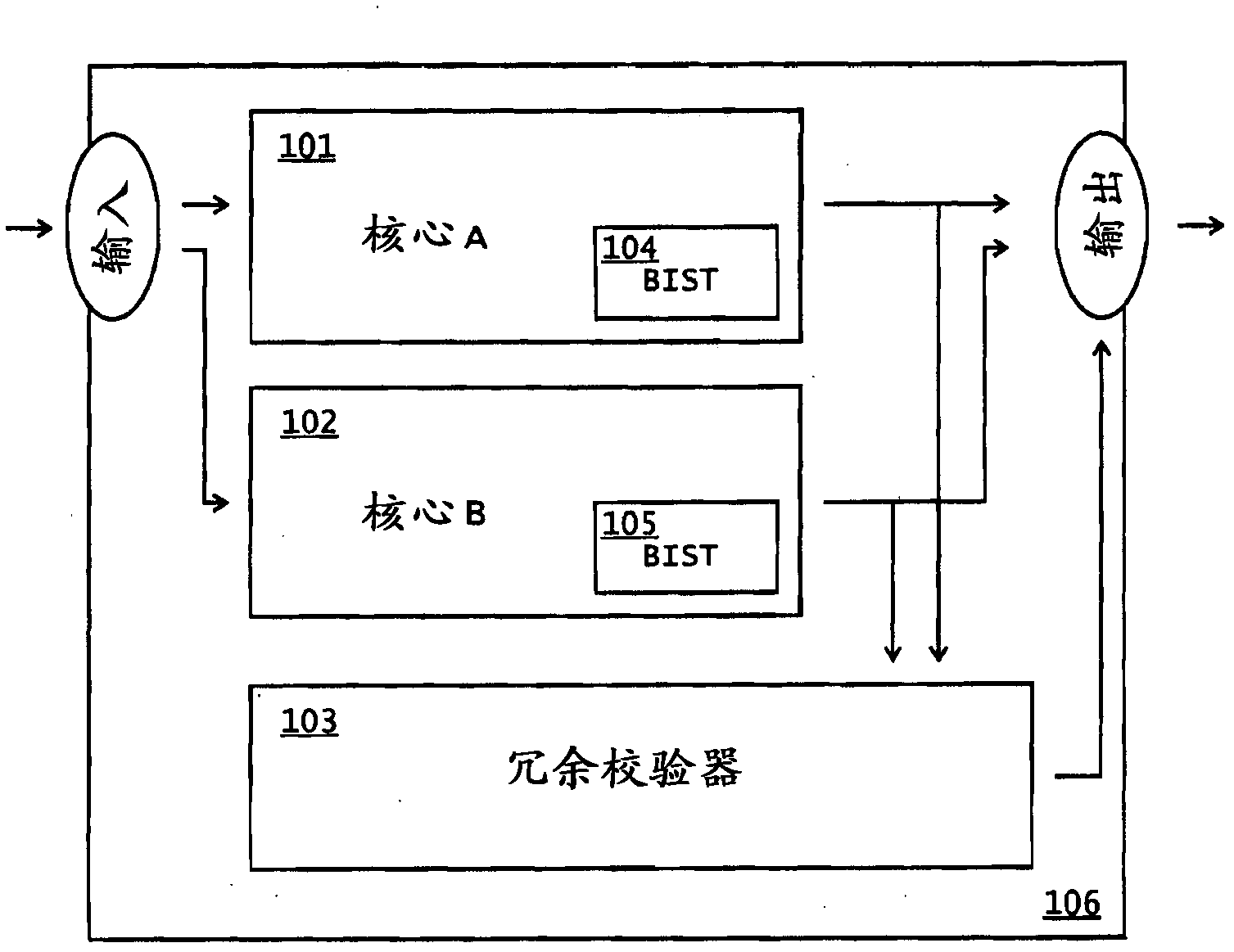
[0025] The main object of the present invention is to provide a highly reliable logic circuit which is guaranteed to perform the intended task when invoked.

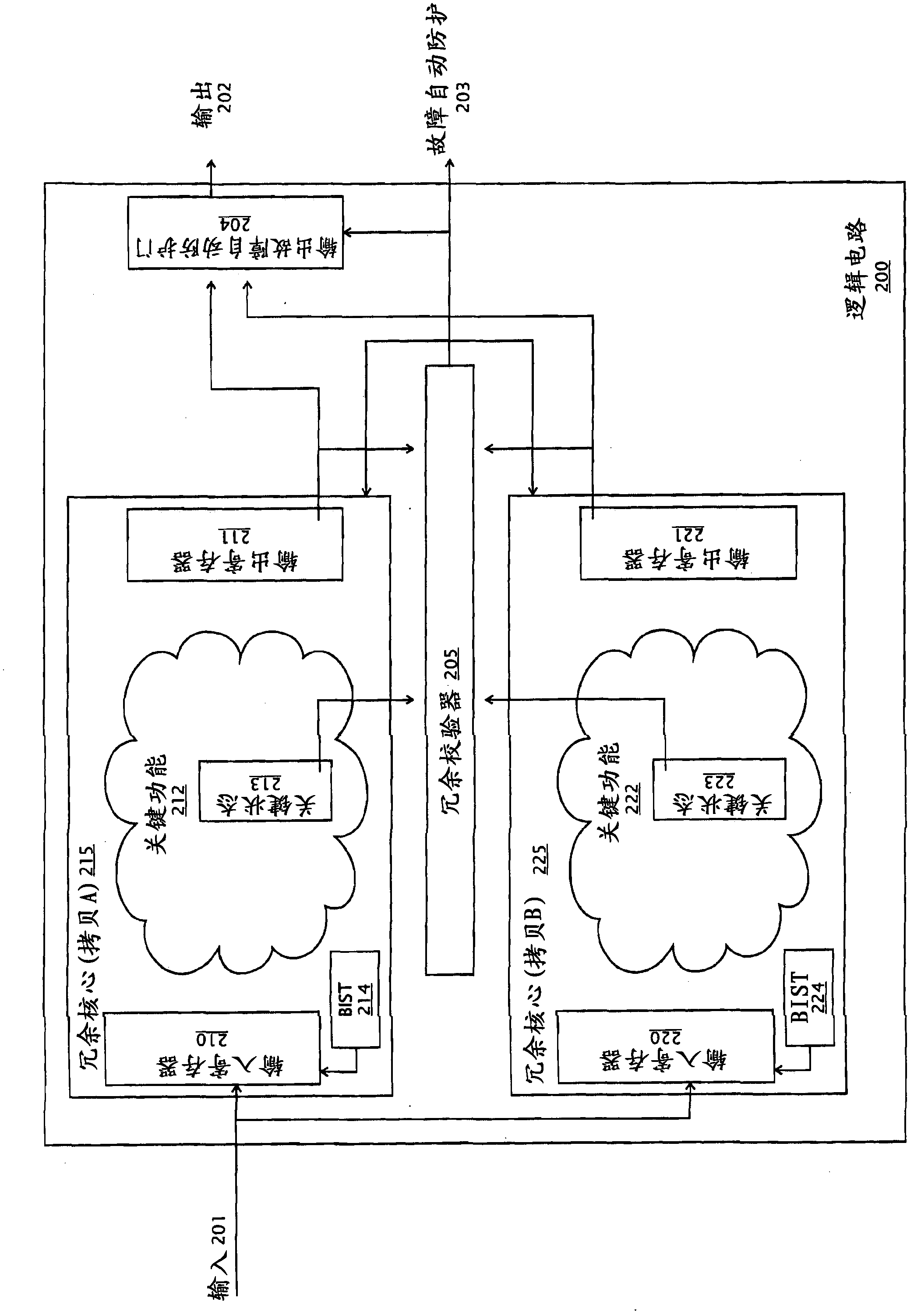
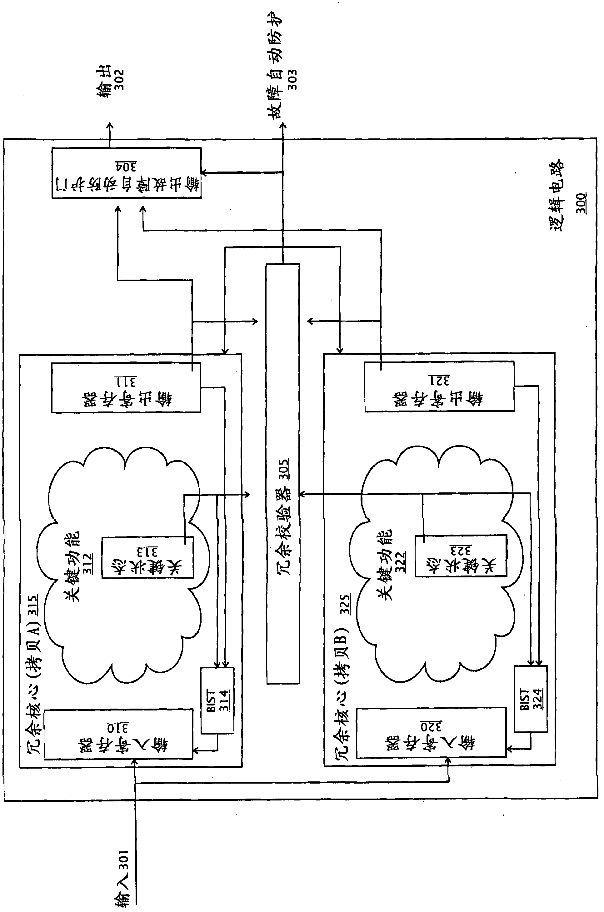
[0026] Another object of the present invention is to provide a method for designing fail-safe logic circuits implemented within a single logic device such as a PAL, CPLD, ASIC, gate array, or FPGA. Alternatively and as such, the logic circuitry is implemented in a combination of multiple logic devices on a single printed circuit board (PCB). Alternatively and as such, they are implemented in combinations of multiple printed circuit boards with one or more logic devices such as PALs, CPLDs, FPGAs, ASICs, or gate arrays.

[0027] The present invention can incorporate redundancy and / or fault tolerance at the application level by having multiple parallel systems capable of performing tasks. One approach is to have two or more parallel systems capable of performing tasks. If one of these systems fails and goes into a fail-s...


PUM


Abstract

The invention relates to fault detection and reduction in a logic circuit. The invention provides a method for monitoring faults of the logic circuit. Particularly, the method aims at building a parallel logic circuit core; the fault is detected by comparing equivalent parallel paths at a key position through a redundancy check device, and any mismatching can result in a preset fault automatic protection operation mode. In addition, with the application of an important technology and the assurance of each parallel path served at a fixed period, the parallel core is checked in a manner of not disturbing any monitored or controlled process. The characteristics are important in some industries, such as a nuclear power industry. At this point, a safe key operation requires a high reliability state as to a logic circuit block which is not always frequently utilized.

Description

[0001] Cross References to Related Applications [0002] This application is a continuation-in-part of US Patent Application No. 12 / 026,703, filed February 6, 2008. The entire prior application is hereby incorporated by reference. technical field [0003] The present invention generally relates to a method for designing high integrity logic circuits. The present invention is particularly directed to safety-related control systems, including nuclear power plant reactor protection systems, where integrity and reliability are paramount. The present invention is particularly directed to implementing these methods in a logic device such as a PAL, CPLD, FPGA, ASIC, or Gate Array, or in a combination of multiple logic devices. The logic device is usually mounted on a printed circuit board. Background technique [0004] Others have attempted to improve the reliability of mission-critical logic components in computerized systems. For example, US Patent 7,290,169 describes a core-...

Claims


Application Information

Patent Timeline
IPC IPC(8): G06F11/16G01R31/28
Inventor S・D・索伦森S・索加尔德
Owner WESTINGHOUSE ELECTRIC CORP
Why Eureka
Try Eureka