Modeling method of optimal power flow model of receiving end power grid security domain

An optimal power flow and receiving-end power grid technology, applied in the direction of electrical digital data processing, special data processing applications, instruments, etc., can solve problems such as dense 220kV power grid, excessive short-circuit current, and weak support

Active Publication Date: 2012-12-26
ELECTRIC POWER RESEARCH INSTITUTE OF STATE GRID SHANDONG ELECTRIC POWER COMPANY +1
View PDF2 Cites 10 Cited by
  • Summary
  • Abstract
  • Description
  • Claims
  • Application Information

AI Technical Summary

Problems solved by technology

The receiving-end system is relatively weak, and the load center lacks strong power support, especially the weak support of the 500kV power grid, resulting in the 220kV power grid being too dense and the short-circuit ...

Method used


Image

  • Modeling method of optimal power flow model of receiving end power grid security domain
  • Modeling method of optimal power flow model of receiving end power grid security domain
  • Modeling method of optimal power flow model of receiving end power grid security domain

Examples


Embodiment 1

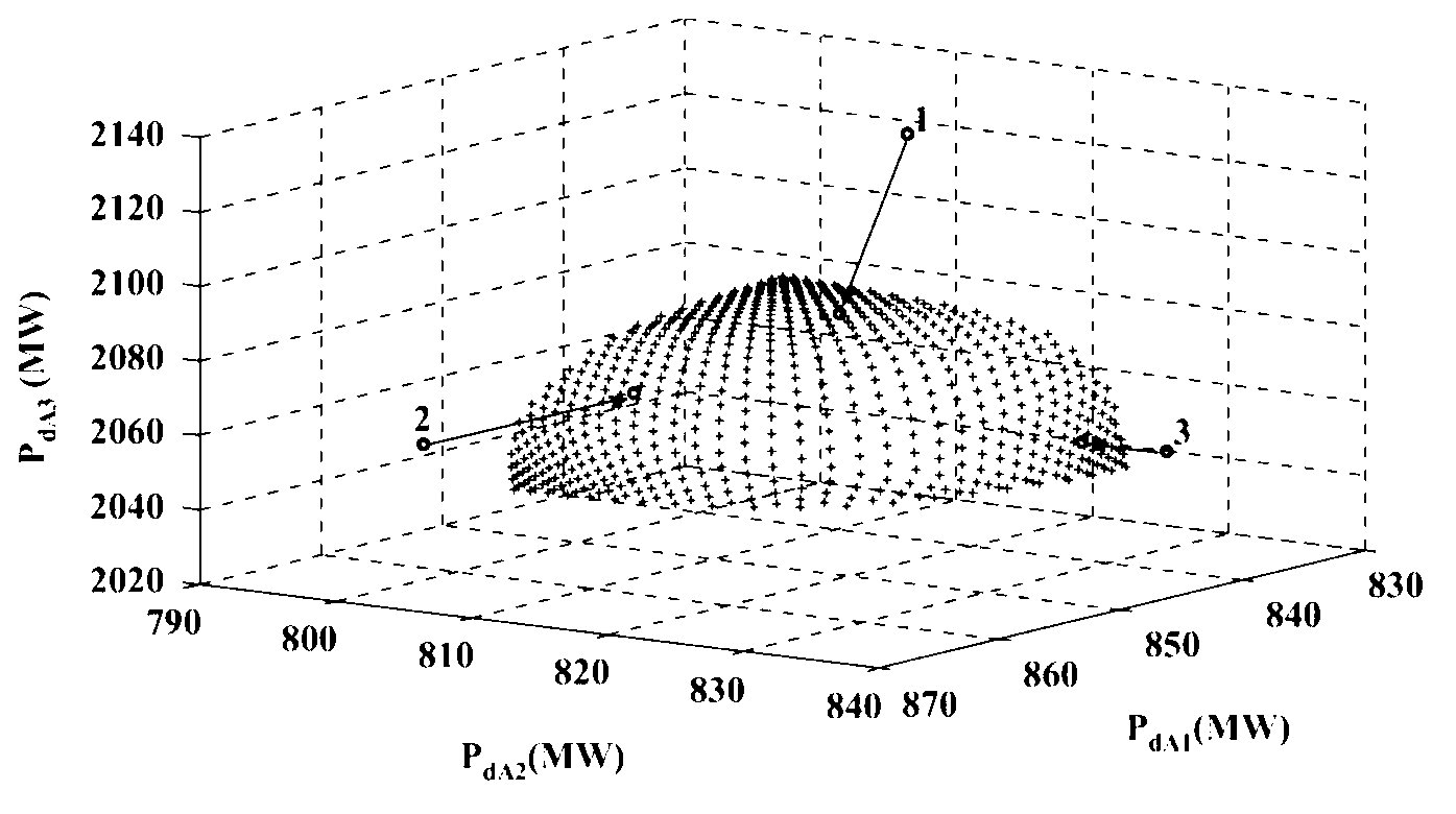
[0161] Such as figure 2 As shown, the original 118-node standard test system is divided into three areas, where area 1 and area 2 each contain 31 loads, and area 3 contains 29 loads. For a standard computer (Core 2 dual-core 2.2Ghz processor, 2G memory), in order to keep the error between input and output within 10-5, it took 156 seconds to obtain the system security domain.

[0162] To test the validity of the proposed optimal power flow model, select P according to Table 2 dA1 , P dA2 And P dA3 Forcing the operating state of the system to jump out of the security domain, figure 2 Three jump points have been marked in, and the bid for load change is assumed to be C dA1 =200$ / MWh, C dA2 =400$ / MWh and C dA3 =600$ / MWh, the solution of the corresponding optimal power flow model is shown in Table 3; analysis shows that in general, the highest bid load P dA1 Reduction ΔPd A1 Minimal, so that the system operating state returns to the security domain.

[0163] Table 2 System test ...

Embodiment 2

[0168] The original 118-node standard test system is divided into four areas, where area 1, area 2 and area 3 each contain 22 loads, and area 4 contains 25 loads. To keep the error between input and output at 10 -5 Within 225 seconds, it took a total of 225 seconds to obtain the system security domain. According to the three-region calculation example, select P dA1 , P dA2 , P dA3 And P dA4 Forcing the system operating state to jump out of the safety zone, as shown in Table 4; suppose the bid of the load change amount is C dA1 =800$ / MWh, C dA2 =100$ / MWh, C dA3 =300$ / MWh and C dA4 =600$ / MWh;

[0169] Table 5-4 System test plan

[0170]

[0171] Table 5-5 System load change

[0172]

[0173]

[0174] The solution of the corresponding optimal power flow model is shown in Table 5; in the four-region calculation example, the highest bid load P dA1 Load P relatively lower than the bid dA2 And P dA3 The reductions are all close to 0, and the four areas that have a greater impa...


PUM


Abstract

The invention discloses a modeling method of an optimal power flow model of a receiving end power grid security domain. The method includes a first step: constructing a system security domain through analysis of stability of a power flow equation, namely stability of quiescent voltage, phase angles and oscillation frequency of a system, and N-1 operation standards, wherein N loads of the system can be converted into M different sets composed in the load direction according to given power generation dispatching standards to generate a critical load matrix for approximate treatment of the security domain; a second step: constructing a dynamic security constraint optimal power flow model; a third step: constructing a self-adaptive neural fuzzy inference system; and a fourth step: training the self-adaptive fuzzy inference system and constructing the optimal power flow model. The optimal power flow model well expounds the operation standards of current electric power system dispatching. The optimal power flow security domain approximation technology based on the self-adaptive fuzzy inference system can be applied to dispatching optimization between receiving end power grid areas after distribution of hierarchy and areas.

Description

Technical field [0001] The invention relates to a modeling method of an optimal power flow model, in particular to a modeling method of an optimal power flow model of a receiving end power grid security domain. Background technique [0002] In the long-term development process of the power system, grid operation planning and system power flow calculation are complementary. On the one hand, in order to ensure the safety and stability of the entire power grid, the formation of power grid planning needs to be based on system power flow calculation; on the other hand, system optimal power flow calculation can improve the stability and economy of power grid planning. The optimal power flow can achieve the predetermined goal and optimal system stable operation state by adjusting the control means available in the system under the specific system operation and safety constraint conditions. Therefore, as the problem of system safety operation becomes increasingly acute and complex, opti...

Claims


Application Information

Patent Timeline
IPC IPC(8): G06F17/50
CPCY02E60/76Y04S40/22Y02E60/00
Inventor 麻常辉张磊蒋哲武乃虎
Owner ELECTRIC POWER RESEARCH INSTITUTE OF STATE GRID SHANDONG ELECTRIC POWER COMPANY
Why Eureka
Try Eureka