Method for transmitting data, network element side and UE (User Equipment) in joint transmission

A technology of user equipment and joint transmission, applied to the network element side and user equipment, third-generation partners, data transmission field in joint transmission

Active Publication Date: 2012-12-26
ZTE CORP
View PDF4 Cites 10 Cited by
  • Summary
  • Abstract
  • Description
  • Claims
  • Application Information

AI Technical Summary

Problems solved by technology

[0005] In view of this, the main purpose of the present invention is to provide a data transmission method, network element side and user equipment in joint transmission, which solves the problem of data transmission when the user equipment accesses two systems at the same time, and helps the network side reasonably Distributing data, which helps to increase the rate of data transmission of user equipment

Method used


Image

  • Method for transmitting data, network element side and UE (User Equipment) in joint transmission
  • Method for transmitting data, network element side and UE (User Equipment) in joint transmission
  • Method for transmitting data, network element side and UE (User Equipment) in joint transmission

Examples


Embodiment 1

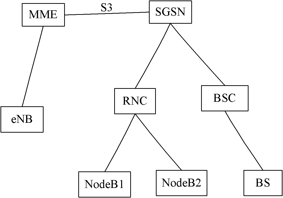
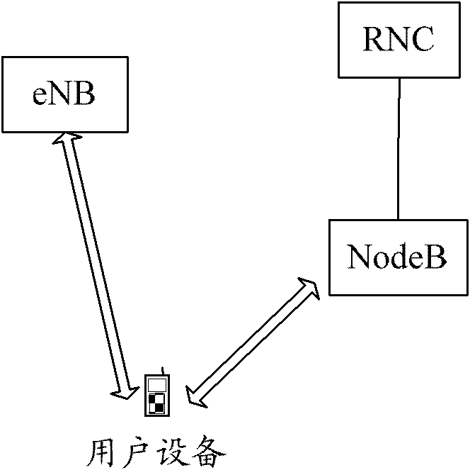
[0106]In this embodiment, the user equipment UE1 resides in the cell 1 under the jurisdiction of the base station 1 in the UMTS system and is in an idle state, and the base station 1 is under the jurisdiction of the RNC. Cell 2 having the same coverage (or overlapping coverage) with cell 1 is governed by eNB 2, and eNB 2 belongs to the LTE system. In the UMTS system, an Iub interface is established between the RNC and the base station 1 . Since the RNC may implement joint transmission with the evolved base station 2 in LTE, a new interface is established between the RNC and the evolved base station 2 for transferring data and control signaling. The establishment of the interface between the RNC and the eNB 2 can be implemented by an operation and maintenance (Operation & Maintenance) server. This embodiment implements a method for downlink data transmission in joint transmission, such as Figure 4 As shown, the method includes the following steps:

[0107] Step 201, UE1 ini...

Embodiment 2

[0139] In this embodiment, the user equipment UE2 accesses the network through the LTE system and is in a connected state, and the UE2 accesses the cell 3 under the jurisdiction of the evolved base station 3, that is, the evolved base station 3 has established an RRC connection for the UE2. The base station 4 in the UMTS system is governed by the RNC, and the coverage area of ​​the cell 4 governed by the base station 4 overlaps with that of the cell 3 .

[0140] The application scenario of this embodiment is: UE2 has established a data radio bearer (DRB, Data Radio Bearer), which is represented by DRB 1 below. If UE2 needs to create a new data radio bearer DRB2, and eNB3 does not have enough resources to meet the QoS parameter requirements of UE2's new DRB2, since eNB3 already knows that UE2 has the ability to support joint transmission when UE2 accesses the network, Therefore, the eNB 3 hopes to use the joint transmission method to enable the UE2 to obtain more radio resource...


PUM


Abstract

Disclosed is a method for sending downlink data in joint transmission. An anchor network element and a non-anchor network element participating in joint transmission adopt a data transmission protocol architecture in which a media access control (MAC) layer distributes a data packet; the MAC layer of the data transmission protocol architecture comprises an MAC-1 entity and an MAC-2 entity located in the anchor network element as well as an MAC-2 entity located in the non-anchor network element; in joint transmission of data, the MAC-1 entity located in the anchor network element distributes a downlink data packet to each MAC-2 entity, and the MAC-2 entity receiving the downlink data packet sends the received downlink data packet to a user equipment. Also disclosed are a method for receiving downlink data and methods for sending and receiving uplink data in joint transmission as well as a corresponding network element side and a corresponding user equipment. Through the solutions of the present invention, the problem of data transmission in a joint transmission mode is solved, reasonable data distribution of the network side is facilitated, and data transmission efficiency of the user equipment is improved.

Description

technical field [0001] The present invention relates to the third generation partnership (3GPP) technology in the field of communication, in particular to a method for data transmission in joint transmission, a network element side and user equipment. Background technique [0002] The architecture of the existing 3GPP access system, such as figure 1 As shown, it includes a radio access network part and a core network part, wherein the radio access network part includes GERAN (GSM EDGE Radio Access Network), Universal Mobile Telecommunications System (UMTS, Universal Mobile Telecommunications System) access network and long-term evolution (LTE , Long Term Evolution) access network. Both GERAN and UMTS access networks are connected to the core network element GPRS Serving Support Node (SGSN, Serving GPRS Support Node), and the LTE access network is connected to the core network element Mobility Management Entity (MME, Mobility Management Entity). GERAN refers to the base sta...

Claims


Application Information

Patent Timeline
Patent Type & Authority Applications(China)
IPC IPC(8): H04W28/16
CPCH04W28/08H04W28/16H04W28/0867H04W28/0861
Inventor 邓云艾建勋
Owner ZTE CORP
Why Eureka
Try Eureka