Connector assembly for solar shingles

A connector assembly, solar technology, used in semiconductor devices, electrical components, renewable energy integration, etc.

Active Publication Date: 2012-12-26
TE CONNECTIVITY CORP
View PDF3 Cites 2 Cited by
  • Summary
  • Abstract
  • Description
  • Claims
  • Application Information

AI Technical Summary

Problems solved by technology

This location of wires and cables may be out of sight, resulting in few homeowners wanting to install solar tiles in their home

Method used


Image

  • Connector assembly for solar shingles
  • Connector assembly for solar shingles
  • Connector assembly for solar shingles

Examples


Embodiment Construction

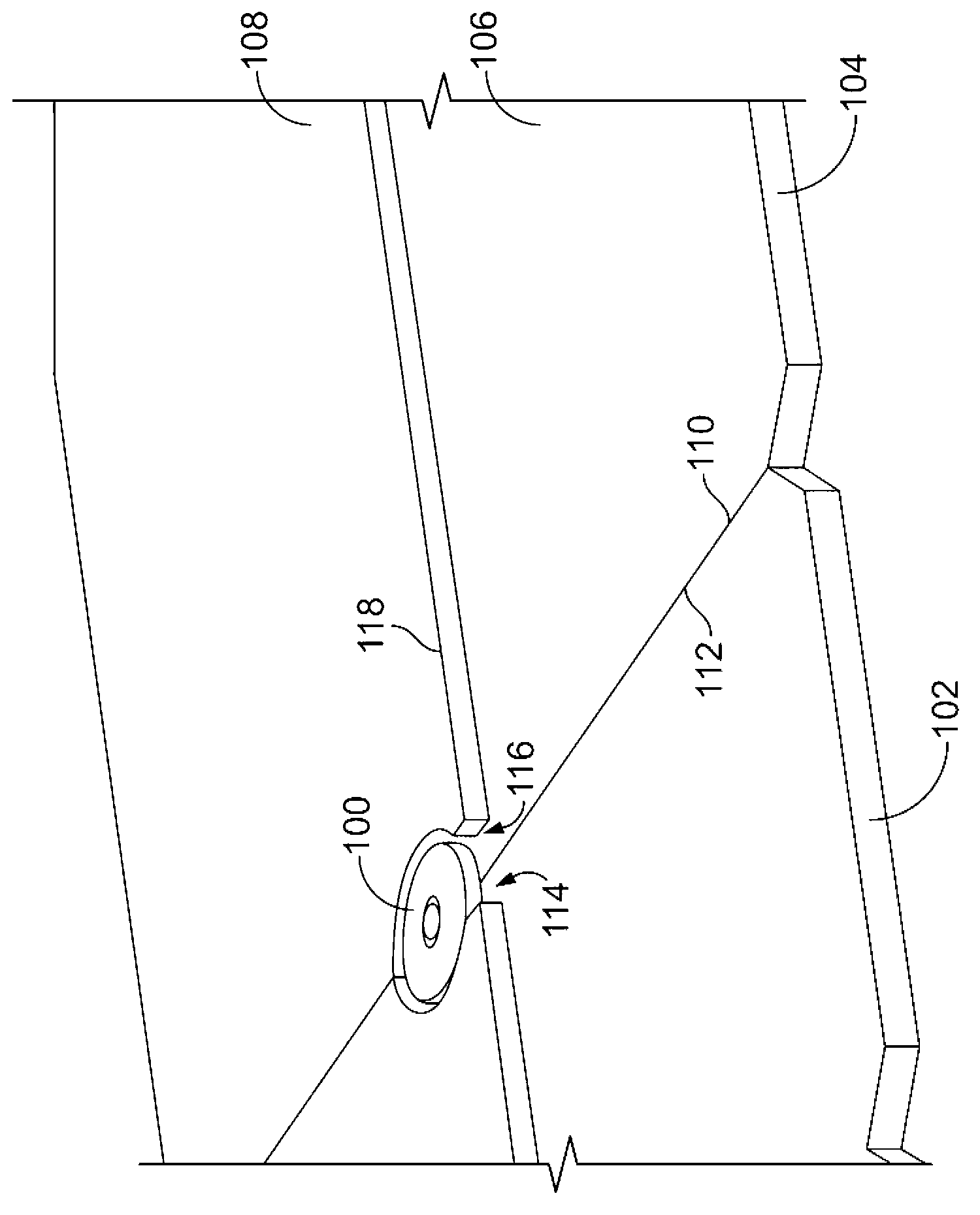
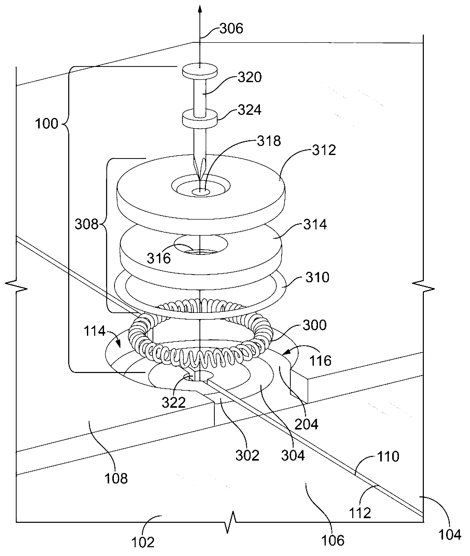
[0017] In one embodiment, a connector assembly for electrically coupling solar tiles is provided. A solar tile includes a photovoltaic portion that converts light into electricity and a support portion that has an upper surface to which other solar tiles may be mounted. The connector assembly includes contacts and a protective covering. The contacts electrically couple the photovoltaic portions of adjacent solar tiles by engaging conductive members disposed in the recesses of the support portions of the solar tiles. The cover protection layer is arranged in the depression of the solar tile. The cover protection layer surrounds the contact between the cover protection layer and the conductive member.

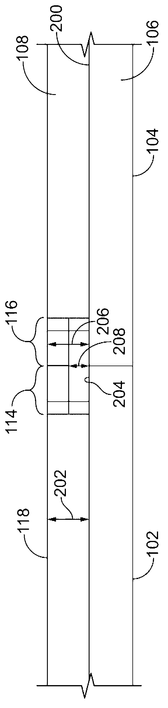
[0018] In another embodiment, another connector assembly is provided. The connector assembly electrically couples the solar tiles that convert light into electricity. The solar tile has a recess extending inwardly from the upper surface to the lower surface and arranged along...


PUM


Abstract

A connector assembly for electrically coupling solar shingles is provided. The solar shingles include photovoltaic sections that convert light into electricity and supporting sections having upper surfaces to which additional solar shingles are mounted. The connector assembly includes a contact and a protective cover. The contact electrically couples the photovoltaic sections of adjacent solar shingles by engaging conductive members disposed in recesses of the supporting sections of the solar shingles. The protective cover is disposed in the recesses of the solar shingles. The protective cover encloses the contact between the protective cover and the conductive members.

Description

technical field [0001] The subject matter herein relates generally to connector assemblies, and more particularly, to connector assemblies that electrically couple solar tiles. Background technique [0002] The ever-increasing demand for renewable energy sources has resulted in an ever-increasing demand for photovoltaic modules. Photovoltaic modules convert incident light into electrical power, such as voltage or current, that can power one or more electrical loads. Previously, some photovoltaic modules have been mounted to roofs or upper surfaces of structures such as commercial buildings and homes. These photovoltaic modules are relatively large and heavy, and are installed to the structure with considerable effort and expense. [0003] Roof tiles incorporating photovoltaic cells or modules have recently been developed. The tiles may be referred to as solar tiles. The tiles are mounted to the roof or upper surface of the structure. Photovoltaic cells or modules in the...

Claims


Application Information

Patent Timeline
Patent Type & Authority Applications(China)
IPC IPC(8): H01L31/048H01L31/02
CPCY02E10/50H01L31/05Y02B10/12H01L31/0483H02S20/25Y02B10/10
Inventor D.E.斯塔尔R.S.古德
Owner TE CONNECTIVITY CORP
Why Eureka
Try Eureka