Switching control circuit and switching power supply device
一种开关控制电路、电路的技术,应用在输出功率的转换装置、电气元件、对过电流起反应的保护等方向,能够解决成本单价增大、IC管理复杂化、制造工艺复杂化等问题
- Summary
- Abstract
- Description
- Claims
- Application Information
AI Technical Summary
Problems solved by technology
Method used
Image

Examples
no. 1 Embodiment approach 》
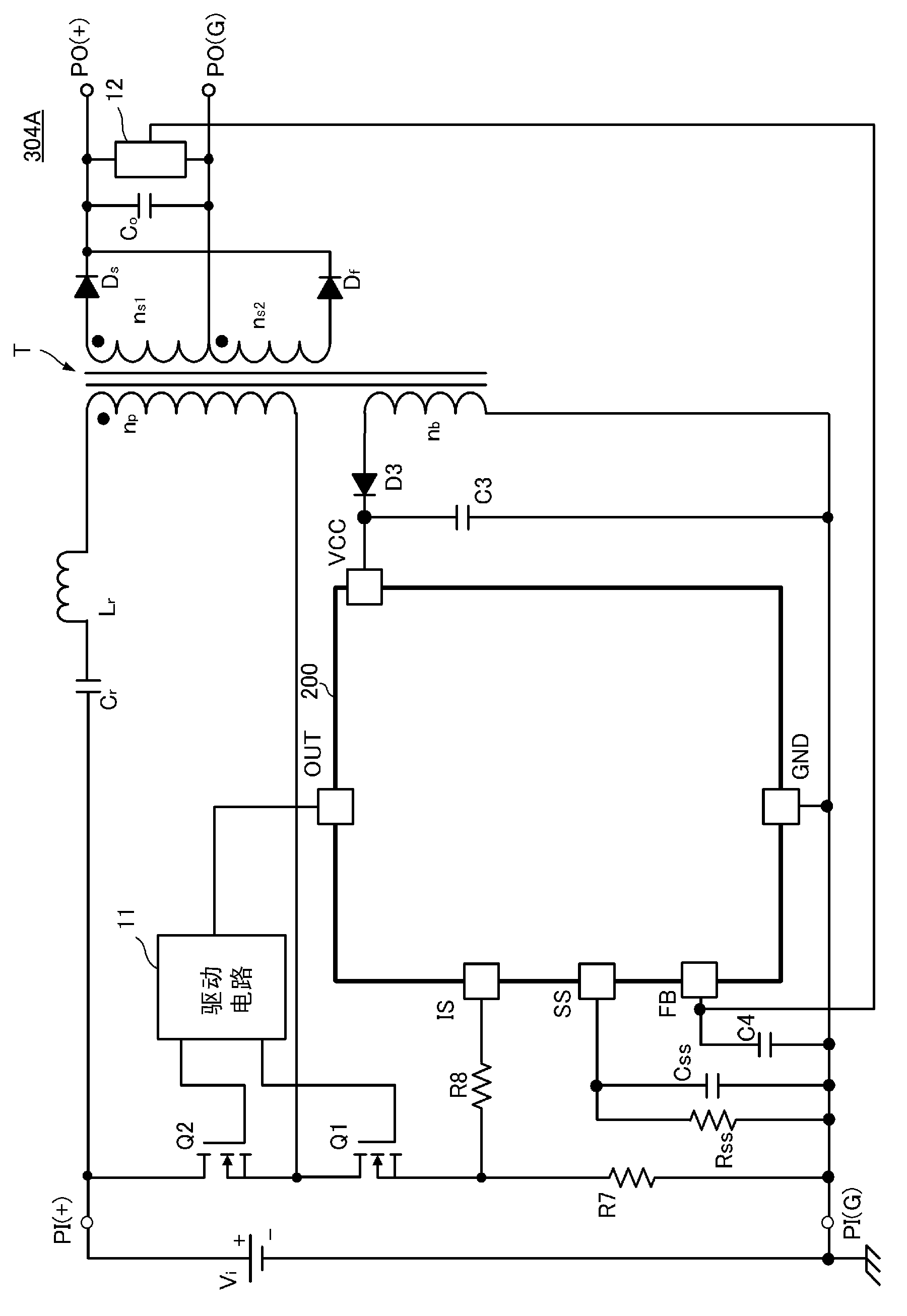
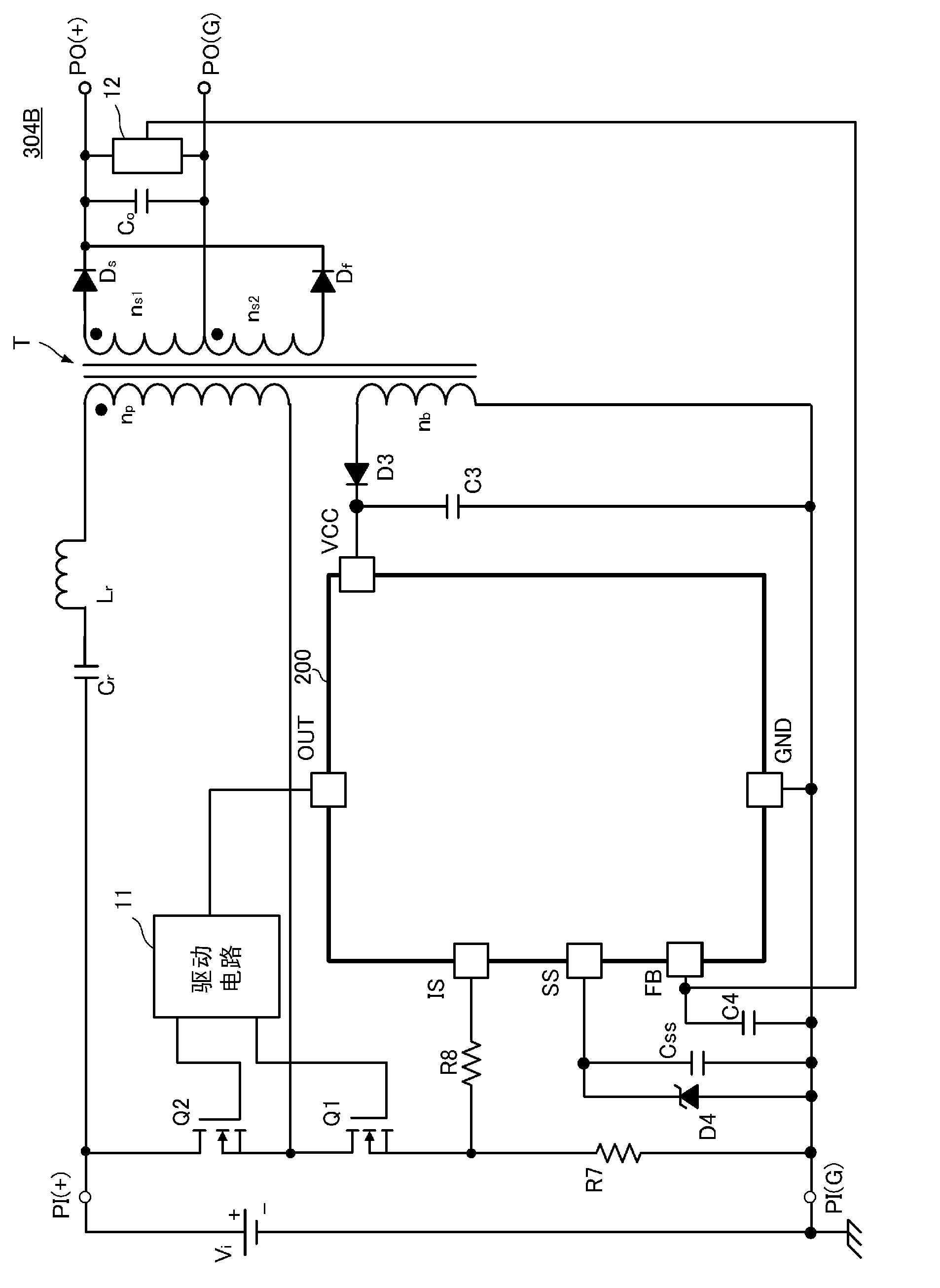
[0059] figure 2 , image 3 It is a circuit diagram of switching power supply devices 304A, 304B according to the first embodiment of the present invention. The switching power supply devices 304A and 304B include the switching control IC 200 corresponding to the switching control circuit of the present invention. exist figure 2 and image 3 Among them, the difference lies in the external circuit connected to the soft start (soft start) terminal SS of the IC 200 for switch control.
[0060] The voltage of the DC input power supply Vi is input between the input terminals PI(+)-PI(G) of the switching power supply devices 304A, 304B. Then, a predetermined DC voltage is output to a load connected between the output terminals PO(+)-PO(G) of the switching power supply devices 304A, 304B.
[0061] A first series circuit in which a capacitor Cr, an inductor Lr, a primary coil np of a transformer T, a first switching element Q1, and a resistor R7 for current detection are connect...
no. 2 Embodiment approach 》
[0102] Figure 6 , Figure 7 It is a circuit diagram of switching power supply devices 312A, 312B according to the second embodiment of the present invention. The switching power supply devices 312A and 312B include the switching control IC 200 corresponding to the switching control circuit of the present invention. The secondary sides of the transformers T of the switching power supply devices 312A and 312B are both in the forward mode. exist Figure 6 and Figure 7 Among them, the connection position of the resonant capacitor Cr on the primary side is different.
[0103] In this way, a rectification and smoothing circuit composed of diodes Ds, Df, inductor Lro, and capacitor Co can also be provided on the secondary side of the transformer T, and a forward mode can be used.
[0104] In addition, since the resonance capacitor Cr on the primary side only needs to be inserted in series in the closed loop formed when the switching element Q2 on the high side is turned on, as...
no. 3 Embodiment approach 》
[0107] Figure 8 It is a circuit diagram of the switching power supply device 313 which concerns on 3rd Embodiment of this invention. The switching power supply device 313 includes the switching control IC 200 corresponding to the switching control circuit of the present invention. The secondary side of the transformer T of the switching power supply device 313 is a forward mode.
[0108] and figure 2 The illustrated switching power supply device 304A is different in that it constitutes a simple forward converter without providing the inductor Lr, the capacitor Cr, and the second switching element Q2.
[0109] In this way, it can also be applied to a simple forward converter and achieve the same function and effect.
PUM
 Abstract
Description
Claims
Application Information
 - R&D Engineer
- R&D Manager
- IP Professional
- Industry Leading Data Capabilities
- Powerful AI technology
- Patent DNA Extraction
Browse by: Latest US Patents, China's latest patents, Technical Efficacy Thesaurus, Application Domain, Technology Topic.
© 2024 PatSnap. All rights reserved.Legal|Privacy policy|Modern Slavery Act Transparency Statement|Sitemap