Subframe dependent physical uplink control channel (pucch) region design

A technology of physical uplink and control channel, applied in transmission path sub-channel allocation, signaling allocation, power management and other directions, which can solve problems such as performance degradation

Inactive Publication Date: 2012-12-26
QUALCOMM INC
View PDF2 Cites 28 Cited by
  • Summary
  • Abstract
  • Description
  • Claims
  • Application Information

AI Technical Summary

Problems solved by technology

Interference due to interfering base stations as well as inter

Method used


Image

  • Subframe dependent physical uplink control channel (pucch) region design
  • Subframe dependent physical uplink control channel (pucch) region design
  • Subframe dependent physical uplink control channel (pucch) region design

Examples


Embodiment Construction

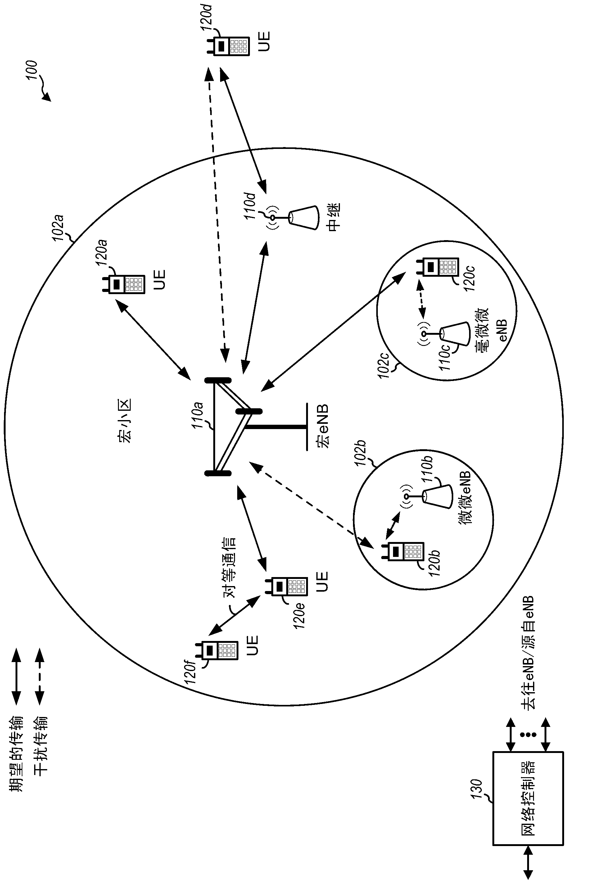
[0026] This application describes techniques for allocating uplink resources in a wireless communication network. According to certain aspects, at least one of a location or a size of resources allocated to a physical uplink control channel (PUCCH) depends on a subframe type, the subframe types including at least a first type in which Transmissions in the first cell are protected by limiting transmissions in the second cell. Resource allocation depending on the subframe type can take advantage of the protection provided for subframes of the first type, allowing a larger area for PUCCH transmissions that can benefit from more robust and reliable transmissions, which can lead to improved system performance. Subframes that are less protected (or subframes that are not protected at all) compared to the first subframe type may have a reduced PUCCH region relative to the PUCCH region of subframes of the first subframe type.

[0027] The techniques described herein may be used in v...


PUM


Abstract

According to certain aspects, resources allocated to a user equipment (UE) for physical uplink control channel (PUCCH) transmissions may be determined in a subframe-type dependent manner. As a result, PUCCH regions for different subframes may vary based on the subframe types.

Description

[0001] Cross References to Related Applications [0002] This application claims priority to U.S. Provisional Application No. 61 / 317,652, filed March 25, 2010, entitled "SUBFRAME DEPENDENT PHYSICAL UPLINK CONTROL CHANNEL (PUCCH) REGION DESIGN," the entirety of which is incorporated by reference The content is expressly incorporated herein. technical field [0003] The present disclosure relates generally to communications, and more specifically, the present disclosure relates to techniques for managing interference by controlling transmit power. Background technique [0004] Wireless communication networks are widely deployed to provide various communication content such as voice, video, packet data, messaging, broadcast, and so on. These wireless networks may be multiple-access networks capable of supporting multiple users by sharing available network resources. Examples of such multiple-access networks include Code Division Multiple Access (CDMA) networks, Time Division ...

Claims


Application Information

Patent Timeline
IPC IPC(8): H04L5/00H04W52/04
CPCH04W72/0446H04W52/244H04W48/08H04L5/0073H04L5/0016H04L5/0007H04W72/0413H04L5/0058H04L5/003H04L5/0053H04W72/21H04W72/23
Inventor 季庭方W·陈D·P·马拉蒂P·加尔
Owner QUALCOMM INC
Why Eureka
Try Eureka