Combine harvester

A technology for combine harvesters and harvesting devices, which is applied in the direction of harvesters, cutters, agricultural machinery and implements, etc. It can solve the problems of hard grains, discharge, etc., and achieve the effect of easy maintenance

Active Publication Date: 2014-11-26
ISEKI & CO LTD
View PDF9 Cites 0 Cited by
  • Summary
  • Abstract
  • Description
  • Claims
  • Application Information

AI Technical Summary

Problems solved by technology

[0004] However, the technique described in Patent Document 1 has the problem that it is difficult to discharge the grain to a position far from the grain tank, and it is difficult to discharge the grain to a transport vehicle that is separated by a field dike or irrigation canal.

Method used


Image

  • Combine harvester
  • Combine harvester
  • Combine harvester

Examples


Deformed example 1

[0066] Such as Figure 11 As shown, in Modification 1, a protective portion 29a is installed in approximately half of the ceiling hole 27 on the side of the valley lifting device 10, and the protective portion 29a is formed of a perforated iron plate with a hole 30 formed therein.

[0067] In Modification 1, when the grains stored in the grain tank 6 are clogged, a thin rod is inserted from the ceiling hole 27 on the opposite side of the grain lifting device 10 where the protection portion 29a is not provided, so that the grains can be eliminated. clogged.

Deformed example 2

[0069] Such as Figure 12 As shown, in Modification 2, a protective portion 29b is installed, and the protective portion 29b is formed with a small-diameter hole 30a capable of inserting a thin rod on the side of the valley lifting device 10, and a large-diameter hole is formed on the opposite side of the valley lifting device 10. 30b, the perforated iron plate of roughly rectangular hole 30c constitutes.

[0070] In Modification 2, in addition to the effect of Modification 1, the rigidity of the protection portion 29b can be increased.

[0071] The insertion port 35 is formed in the front side upper part of the left wall 22a, and this insertion port 35 communicates with the grain raising cylinder 10a. The insertion port 35 is formed in an oblique posture of front, bottom and rear, and an imaginary line L1 drawn from the center of the insertion port 35 intersects with the approximate center in the left-right direction of the lower end side of the left wall 22a. In addition, ...


PUM


Abstract

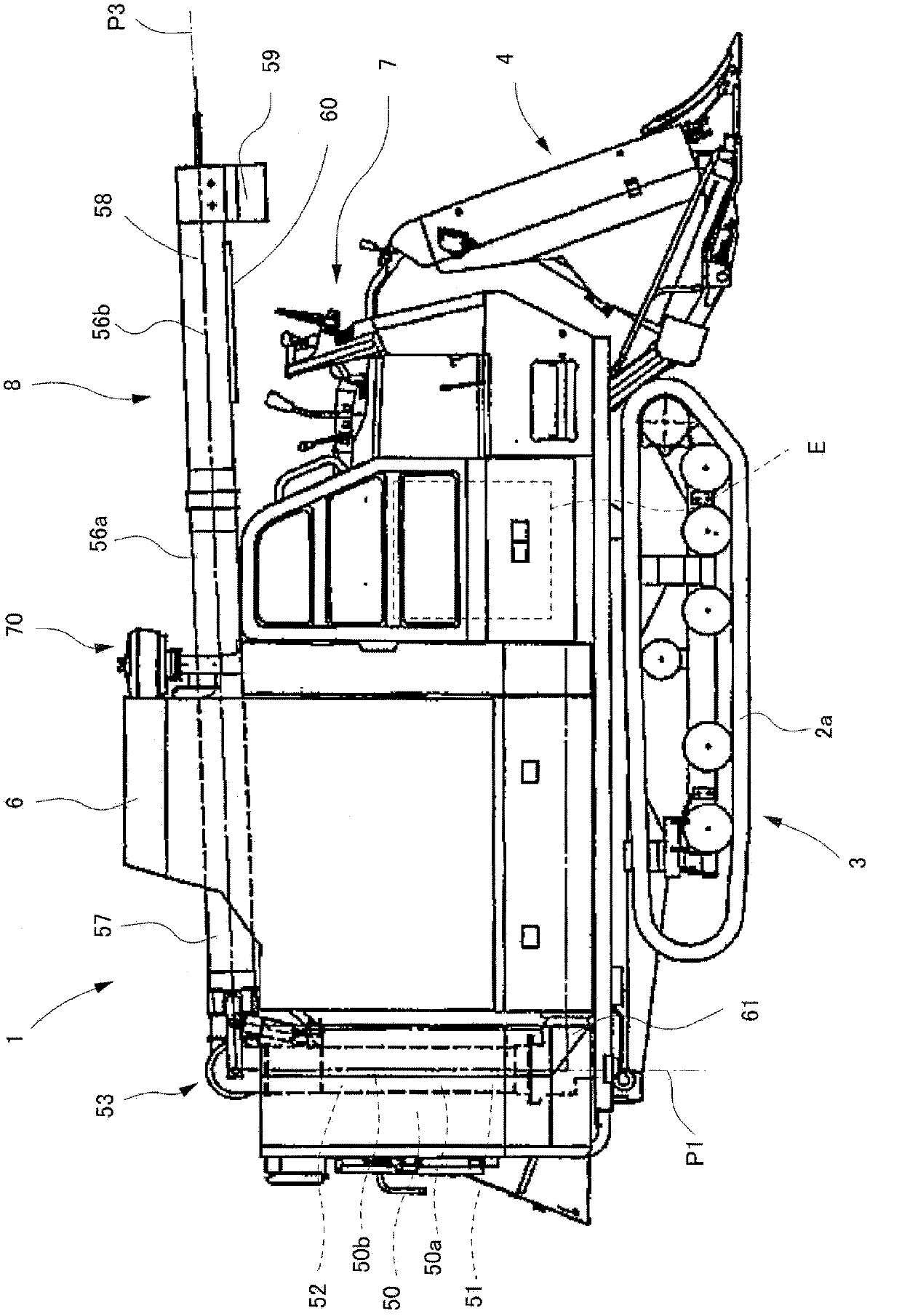
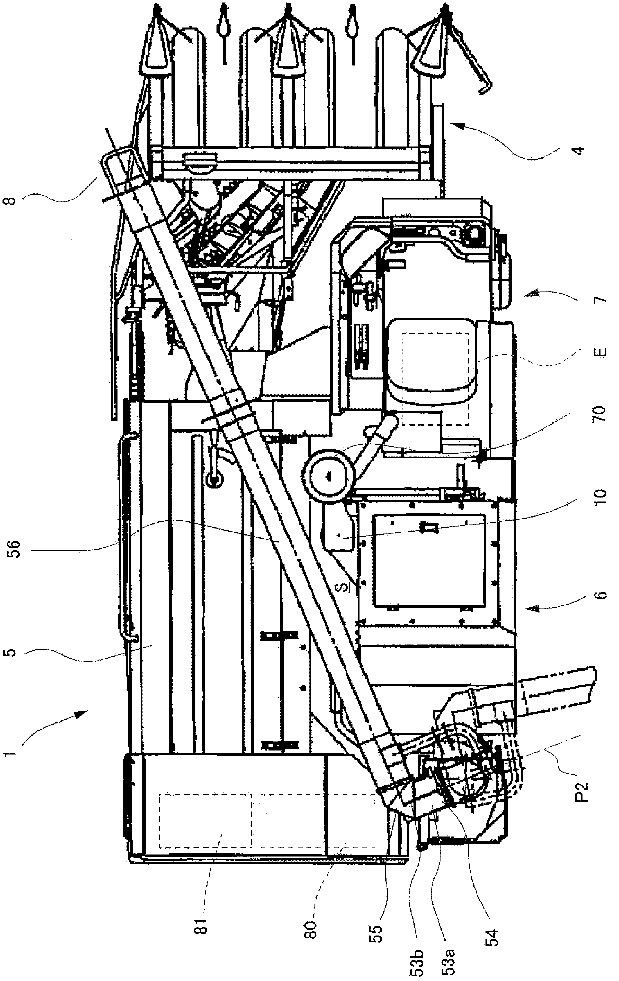
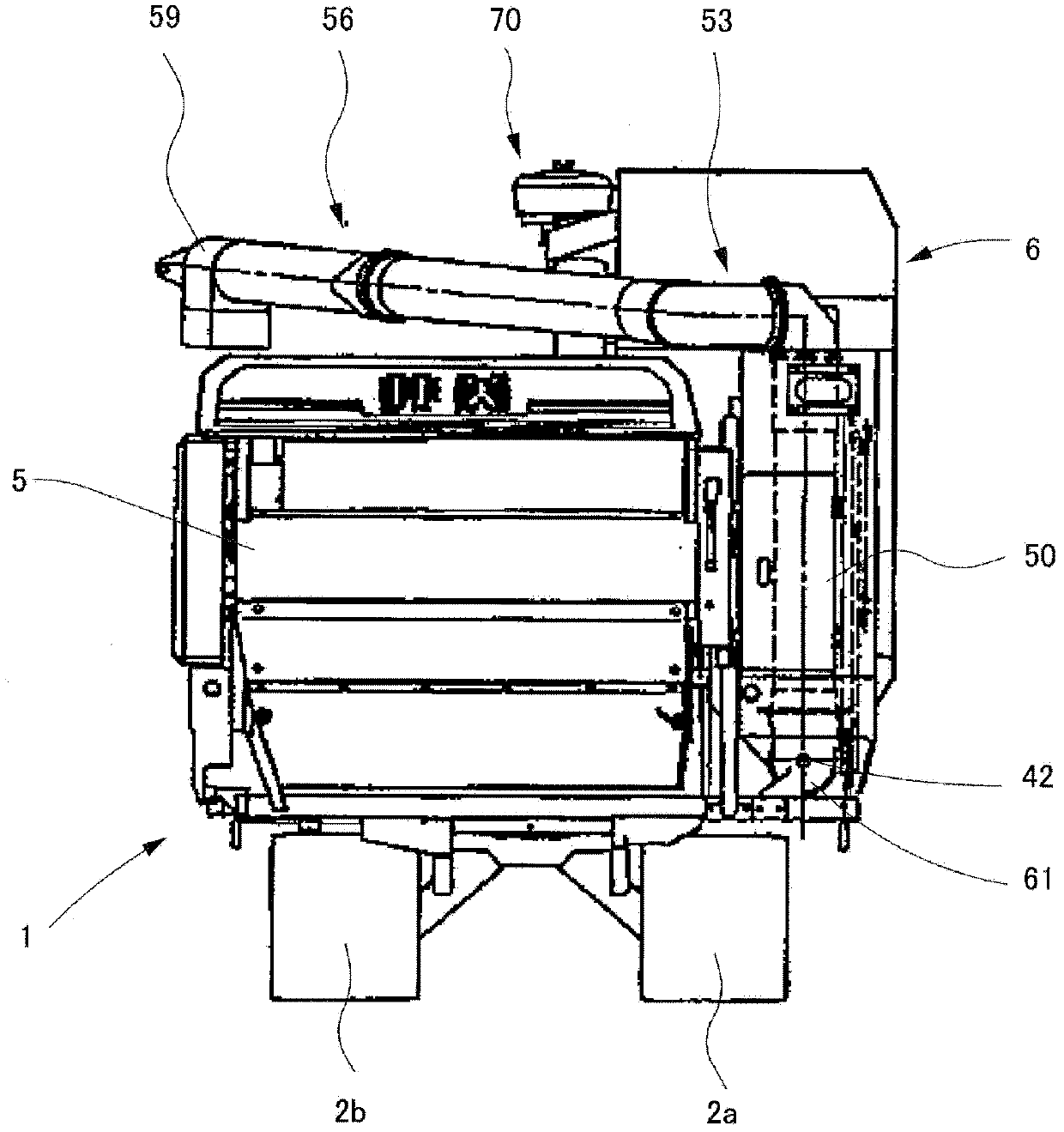
The utility model provides a combine harvester which improves working efficiency of grain discharging of the combine harvester and can easily conduct maintenance on a grain box. A shaft center of a discharge auger (42) arranged in the bottom part of the grain box (6) is disposed at a position which is adjacent to the outer side of the body compared with the outer side end of a track (2a) at the right side. The bottom of a hopper part (40) at the bottom of the grain box (6) is provided with a gate (45) capable of free opening and closing.

Description

technical field [0001] The invention relates to a combine harvester having a grain box and a pre-cleaner. Background technique [0002] Such a combine harvester is known, which is provided with a grain raising device that transfers the grains from the threshing device to the grain box, and has a discharge screw that transfers the grains in the grain box to the outside (patent document 1). [0003] Patent Document 1: Japanese Publication No. 60-147243 [0004] However, the technique described in Patent Document 1 has problems in that it is difficult to discharge the grains to a position far from the grain tank, and it is difficult to discharge the grains to transport vehicles such as dikes or irrigation ditches across the field. Contents of the invention [0005] Therefore, the main subject of this invention is to overcome the said subject, and a sub-subject is to realize the combine which can perform maintenance and inspection of a grain tank easily. [0006] The presen...

Claims


Application Information

Patent Timeline
Patent Type & Authority Patents(China)
IPC IPC(8): A01D41/00A01F12/44A01F12/46A01F12/60
CPCA01D41/1208A01F12/46
Inventor 长井敏郎广瀬雅一
Owner ISEKI & CO LTD
Why Eureka
Try Eureka