Harvester

A harvester and body technology, which is applied in the directions of harvesters, dryers, cutters, etc., to achieve the effects of being conducive to operation, simple installation structure, and bright lighting range

Inactive Publication Date: 2013-01-02
KUBOTA CORP
View PDF1 Cites 3 Cited by
  • Summary
  • Abstract
  • Description
  • Claims
  • Application Information

AI Technical Summary

Problems solved by technology

However, when turning the machine body at one end of the row in order to switch from a harvested row to an unharvested adjacent row, how to easily and accurately perform the alignment of the adjacent row still needs to be improved. room

Method used


Image

  • Harvester
  • Harvester
  • Harvester

Examples


no. 1 Embodiment approach

[0040] The overall composition of the combine harvester

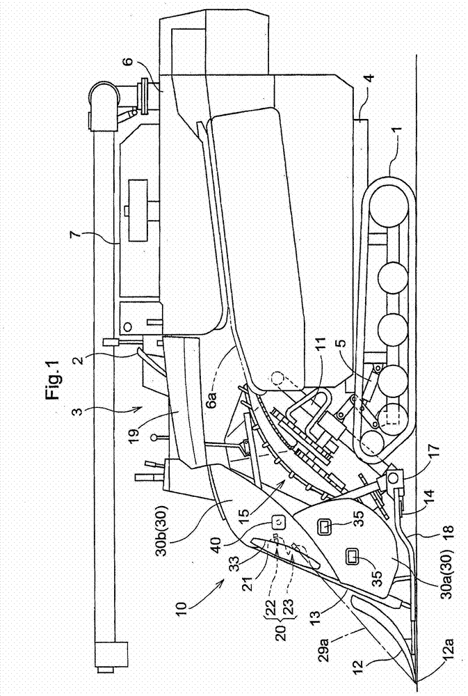
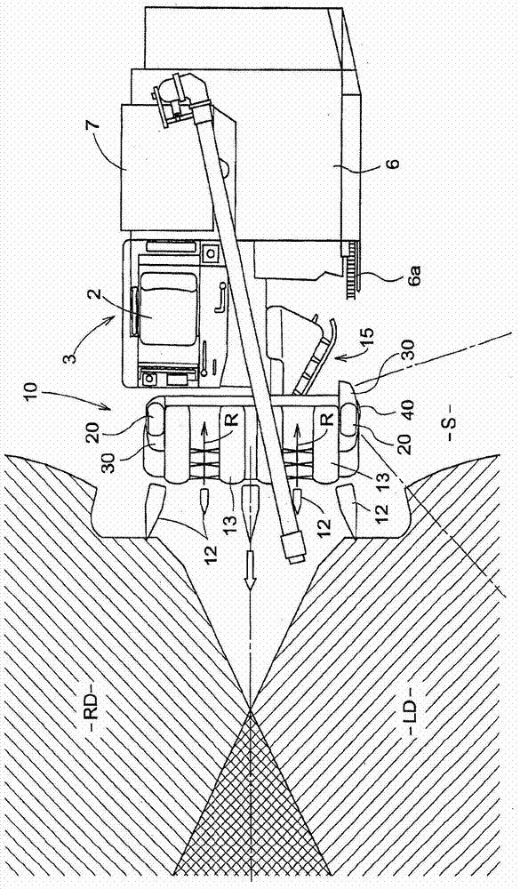
[0041] exist figure 1 , 2 The figure shows the whole side view and the whole top view of the combine harvester which harvests rice, wheat, etc. This combine harvester is equipped with: a self-propelled body that travels with a crawler belt traveling device 1 (hereinafter simply referred to as a body), and a power unit provided at a front portion on one side of the body. The power unit includes a ride-on driving unit 3 on which a driver's seat 2 and the like are mounted, and is driven by the power of an engine (not shown) located below the driver's seat 2 . The pre-processing part frame main body 11 of the pre-harvesting processing part 10 is swingably connected to the front part of the frame 4 of a machine body around the horizontal axis P. As shown in FIG. One side of the rear portion of the frame 4 is provided with a threshing device 6 and a grain box 7 .

[0042] When the lift cylinder 5 provided at the rear l...

no. 2 Embodiment approach

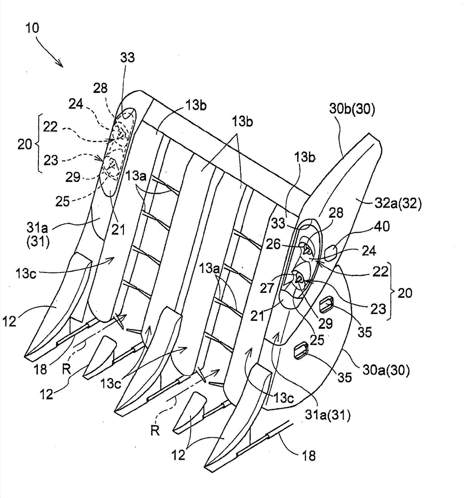
[0081] Figure 15 Showing the headlight device 20 of the second embodiment of the harvester of the present invention, in the headlight device 20 , the lens 21 is provided with an upper side refractor corresponding to the bulb 28 of the upper side headlight 22 . The light projecting portion 21 a and the lower refracting light projecting portion 21 b corresponding to the bulb 29 of the lower headlight 23 .

[0082] The upper refraction light projection part 21a is provided with a refraction light projection characteristic for refraction and projection of the light from the bulb 28, so that the irradiation range of the light emitted from the bulb 28 and irradiated from the upper side refraction light projection part 21a is irradiated. , is the same as the irradiation range formed by the upper headlamp 22 provided with the above-mentioned two types of reflector portions 24a, 24b.

[0083] The lower refraction light projection part 21b is equipped with a refraction light projectio...


PUM


Abstract

To obtain a harvester capable of suitably irradiating the front side and simultaneously traveling on a work travel and also on a moving travel, in advantageous states on the aspects of a structure and operations. This harvester in which headlight devices (20) are fixed to a front harvesting portion (10) connected to a self-propelled machine frame so as to be freely operated in a state capable of being swung into a lower work state or into an upper non-work state is characterized in that the irradiation directions of the headlight devices (20) are set so that the headlight devices (20) irradiate fixed grass dividers (12) and the ground in front of the fixed grass dividers (12), in a state that the front harvesting portion (10) is lowered in the lower work state and so that the headlight devices (20); irradiate the ground separated forward from the self-propelled machine frame than a case that the front harvesting portion (10) is in the lower work state, in a state that the front harvesting portion (10) is lifted in the upper non-work state.

Description

technical field [0001] The present invention relates to a harvester such as a combine harvester, and more specifically, to a harvester equipped with a pre-harvesting processing unit connected to a front portion of a body and having a headlight device. Background technique [0002] There is the conventional harvester of headlamp device, for example, in Japan's real open No. 63-23143 communique (referring to page 2~5, Figure 1 ~ Figure 3 ), Japanese Patent Application Laid-Open Publication No. 10-136758 (refer to [0015] paragraph, [0024] paragraph) have been disclosed. [0003] The headlight device of any above-mentioned harvester is all used for illuminating the place ahead of the body specially, lights up at night and guarantees the field of view relative to the plant stems in the harvesting object row when going straight. However, when turning the machine body at one end of the row in order to switch from a harvested row to an unharvested adjacent row, how to easily and ac...

Claims


Application Information

Patent Timeline
Patent Type & Authority Applications(China)
IPC IPC(8): A01D41/02A01D41/12
CPCF26B3/02F26B9/08F26B25/04Y02W30/20B09B3/40
Inventor 片山靖彦池田修平河濑宗之征矢保川村学司楠忠桝谷一洋
Owner KUBOTA CORP
Why Eureka
Try Eureka