Stopping zipper puller

A zipper puller and stop technology, which is applied in the field of zipper products, can solve the problems of zipper puller self-locking failure, self-locking zipper puller is difficult to use, etc., and achieve the effect of a firm lock

Active Publication Date: 2013-01-02
义乌市可佩智能科技有限公司
View PDF9 Cites 2 Cited by
  • Summary
  • Abstract
  • Description
  • Claims
  • Application Information

AI Technical Summary

Problems solved by technology

[0003] However, since the self-locking zipper pull implements self-locking by exerting an elastic force on the brake hook through the elastic piece, the brake hook may be damaged when the elastic piece fails or the zipper pull is subjected to a large external pulling force. Release the self-locking, so that the self-locking of the zipper head is invalid
This makes it difficult for the self-locking zipper pull to be used on products such as bags that require a strong locking force

Method used


Image

  • Stopping zipper puller
  • Stopping zipper puller
  • Stopping zipper puller

Examples


Embodiment Construction

[0011] Below in conjunction with accompanying drawing and specific embodiment the present invention will be further described:

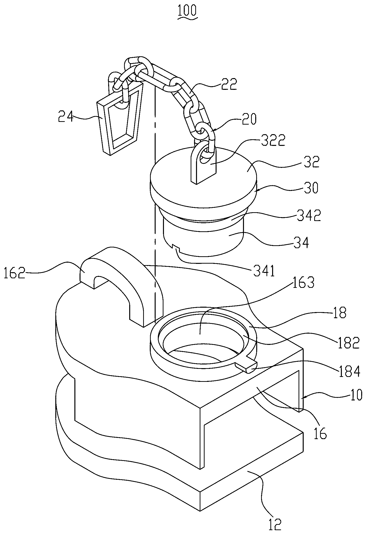
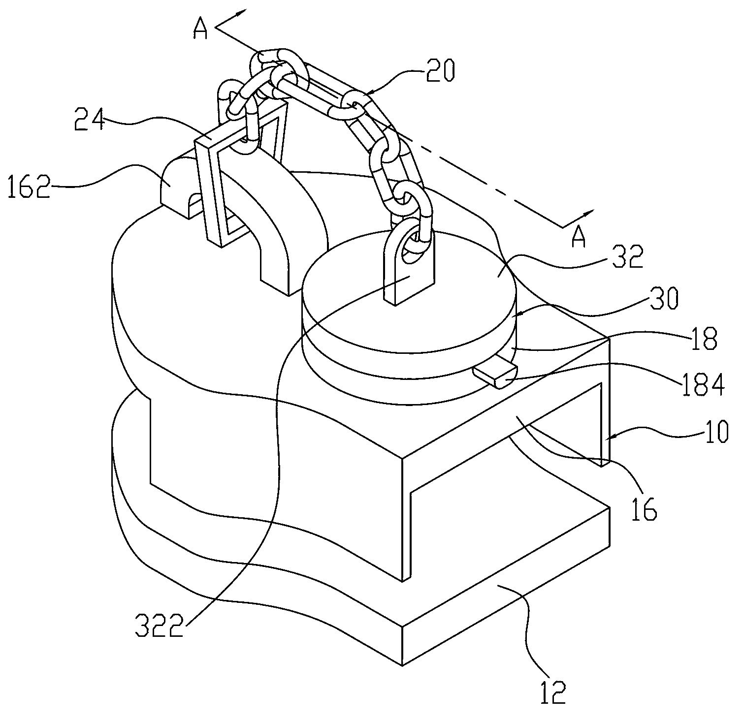
[0012] see figure 1 , The stop type zipper puller 100 of the first embodiment of the present invention includes a slider slider 10 , a handle body 20 and a stopper 30 . Both the handle body 20 and the stopper 30 are connected to the slider 10 . The stopper 30 is connected with the handle body 20 .

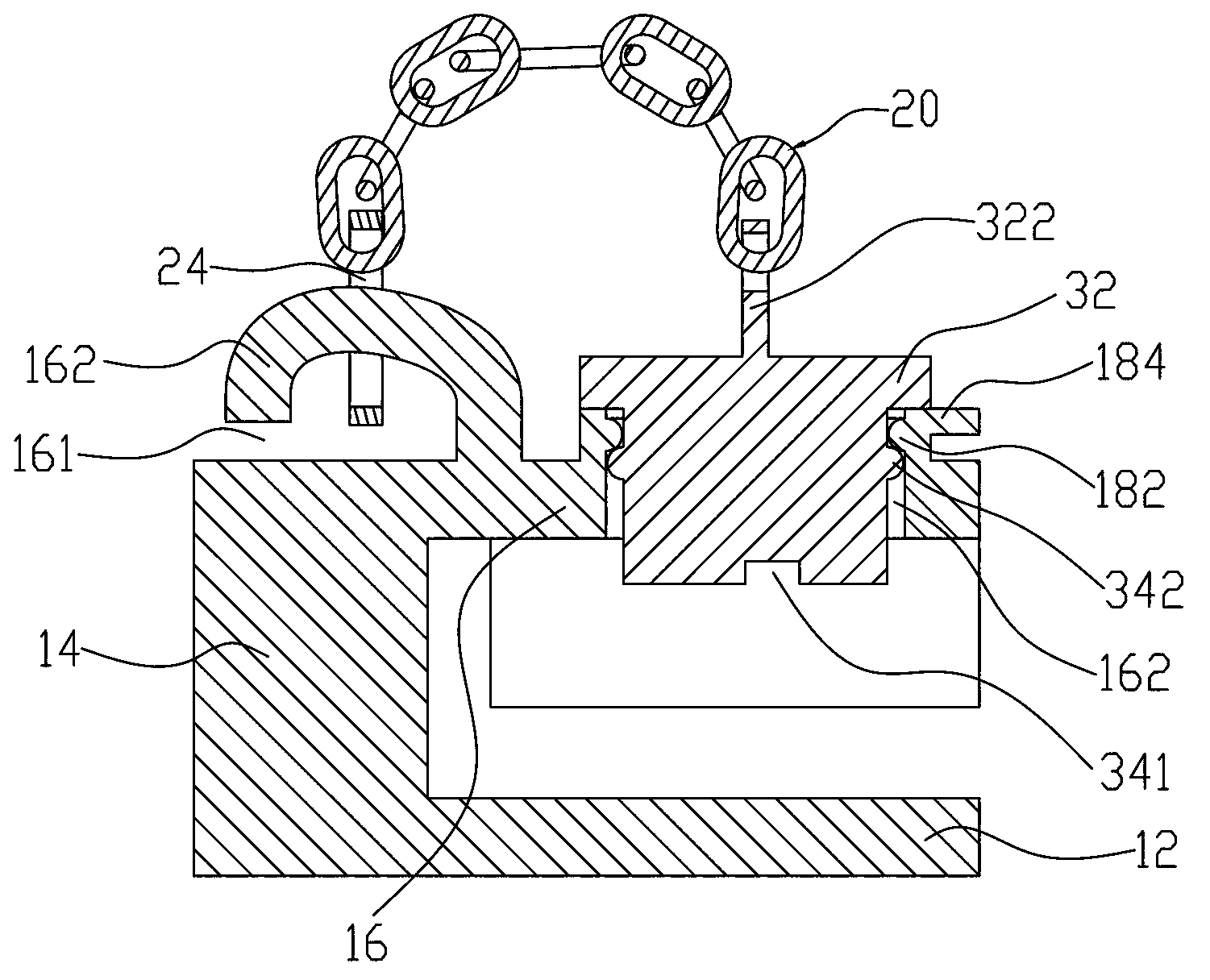
[0013] Please refer to Figure 1 to Figure 3 , the slider slider 10 is made of metal material, which includes a lower wing 12 , a connecting column 14 , an upper wing 16 and a limiting member 18 . The upper wing 16 , the connecting column 14 and the lower wing 12 are connected to each other to form a Y-shaped slideway for two rows of fastener elements (not shown) on the zipper belt to pass through. The limiting member 18 is disposed on the top surface of the upper wing 16 .

[0014] The upper wing 16 is provided with an elephant trunk 162 close to th...


PUM


Abstract

A stopping zipper puller comprises a puller slide block and a pull sheet body, wherein the puller slide block comprises a lower wing plate, a connection column and an upper wing plate; the lower wing plate, the connection column and the lower wing plate form a slideway; one end of the pull sheet body is connected to the upper wing plate; the stopping zipper puller also comprises a retainer; the retainer comprises a head part and a stopping part; the other end of the pull sheet body is connected to the head part; a through hole is arranged in the upper wing plate far away from the connection column; and the retainer is detachably arranged in the through hole, and the stopping part of the retainer extends into the slideway. The stopping zipper puller disclosed by the invention has the advantages that the lock is firm.

Description

technical field [0001] The invention relates to a zipper product, in particular to a stop type zipper head. Background technique [0002] Existing zipper sliders can be roughly divided into self-locking zipper sliders and non-self-locking zipper sliders. Non-self-locking zipper sliders may slide along the zipper tape under non-human conditions, while self-locking zipper sliders can prevent sliding under non-human operating conditions through a specially designed self-locking mechanism. The Chinese Utility Model Patent No. 02285335.9 announced on December 10, 2003 discloses a self-locking zipper puller, which includes a zipper puller body, a brake hook piece, a set of resisting elastic pieces and a cap. The end surface of the zipper slider body is provided with a fitting part and a slot, the cap is fixed on the fitting part, and the braking hook is embedded in the slot. A resisting elastic piece is placed between the inner wall of the cap and the upper end surface of the br...

Claims


Application Information

Patent Timeline
Patent Type & Authority Applications(China)
IPC IPC(8): A44B19/30
Inventor 李甫文
Owner 义乌市可佩智能科技有限公司
Why Eureka
Try Eureka