Continuous stamping bending die

A stamping, bending and die base technology, applied in metal processing equipment, forming tools, manufacturing tools, etc., can solve problems such as increasing die cost and die maintenance cost, inability to continuously and automatically feed processing, and unavoidable misprocessing, etc., to reduce The effect of mold maintenance cost, improving production and processing efficiency, and reducing mold cost

Inactive Publication Date: 2013-01-02
JIANGSU RONGTENG PRECISION COMPONENTS
View PDF8 Cites 9 Cited by
  • Summary
  • Abstract
  • Description
  • Claims
  • Application Information

AI Technical Summary

Problems solved by technology

[0002] Metal stamping and bending materials are widely used in the processing and production of automobile sheet metal parts. Metal bending materials with simple structures can be processed by bending machines and punched by punches, but the processing efficiency is very low, so bending molds are used for processing. mass production
The traditional bending die has only one set of forming male die and female die. It can only perform one bending to complete one bending action, and there is no punching action. For the materials that need to be stamped, twice bent and cut, they need to be prepared separately. Several sets of molds increase the cost of molds and mold maintenance, and the production efficiency is not high. Continuous automatic feeding and processing cannot be performed. Moreover, traditional bending molds do not have misfeeding detection pins, which cannot avoid misprocessing, resulting in waste of materials.

Method used


Image

  • Continuous stamping bending die
  • Continuous stamping bending die
  • Continuous stamping bending die

Examples


Embodiment Construction

[0019] The present invention will be described in detail below in conjunction with accompanying drawings and specific preferred embodiments, so that the advantages and features of the present invention can be more easily understood by those skilled in the art. range is limited.

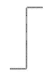
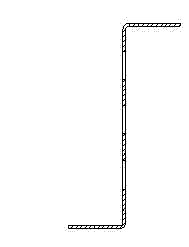
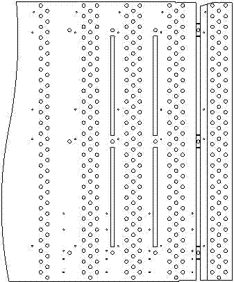
[0020] see Figure 1 to Figure 4 , the continuous stamping and bending die of the present invention comprises: an upper mold base 8, a first end face 23, an upper backing plate 5, a fixing plate 6, a stop plate 10, a stripping plate 11, a pressing block 13, a lower floating block 14, a lower Die base 15, lower die angle 16, lower supporting plate 17, lower bending block 18, material guide plate 19, floating material block 20, lower backing plate 21 and lower template 22, the upper die base 8 is located in the continuous stamping The uppermost end of the bending die, the lower supporting plate 17 is located at the lowermost end of the continuous stamping bending die, the upper backing plate 5 is locat...


PUM


Abstract

The invention discloses a continuous stamping bending die, which comprises an upper die base, a first end face, an upper pad, a fixed plate, a stopped baffle, a stripper plate, a material press block, a lower material floating block, a lower die base, a lower die angle, a lower support plate, a lower bending block, a material guide plate, a floating plate, a lower pad and a lower die plate; the continuous stamping bending die also comprises a plurality of punch heads, a guide pillar, a miscarriage detection pin and a slide block which are arranged on the upper die base. In this way, the continuous stamping bending die can finish punching, cutting off and two bending actions on a set of moulds, and simultaneously, the continuous stamping bending die is also equipped with a punching slide block; two kinds of standard products of the punching can be realized through installing or withdrawing the slide block, thereby enlarging the applicability of the mold, avoiding multiple sets of moulds, reducing the mould cost and the mould maintenance cost, greatly improving the processing efficiency of production, and realizing the continuous processing, so that the batch production is suitable; in addition, the continuous stamping bending die is equipped with the miscarriage detection pin so as to avoid processing wrongly and saving materials.

Description

technical field [0001] The invention relates to a metal plate part processing die, in particular to a continuous stamping and bending die. Background technique [0002] Metal stamping and bending materials are widely used in the processing and production of automobile sheet metal parts. Metal bending materials with simple structures can be processed by bending machines and punched by punches, but the processing efficiency is very low, so bending molds are used for processing. Mass production. The traditional bending die has only one set of forming male die and female die. It can only perform one bending to complete one bending action, and there is no punching action. For the materials that need to be stamped, twice bent and cut, they need to be prepared separately. Several sets of molds increase mold costs and mold maintenance costs, and the production efficiency is not high, and continuous automatic feeding and processing cannot be performed. Moreover, traditional bending ...

Claims


Application Information

Patent Timeline
Patent Type & Authority Applications(China)
IPC IPC(8): B21D37/10
Inventor 杨荣
Owner JIANGSU RONGTENG PRECISION COMPONENTS
Why Eureka
Try Eureka